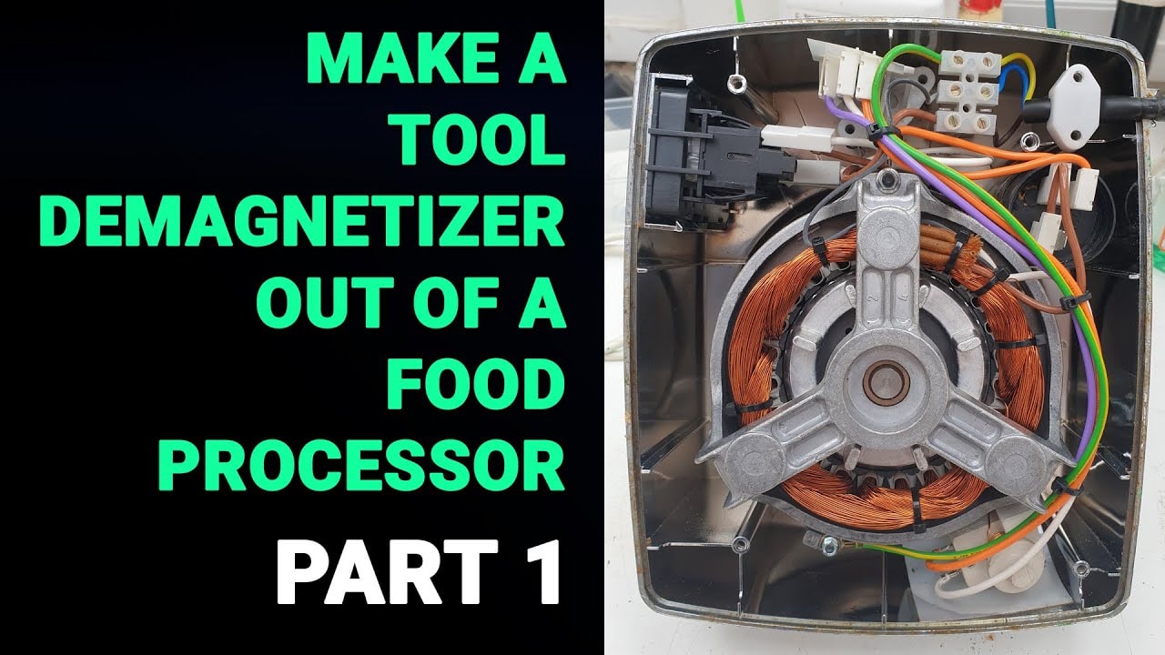

I needed to make a tool demagnetizer for a very simple reason. I’d done something a bit daft.
A while back I was measuring some rather enthusiastic neodymium magnets with my nice Mitutoyo calipers. As you can probably predict, that was not one of my finer moments. The calipers became magnetised, and from then on they started picking up swarf, filings and every other bit of workshop muck they could find.
That is no good at all when you’re trying to measure accurately and there’s effectively 1.7 mm of crud stuck between the jaws.
So this project was born of necessity, which is often how the best shed engineering jobs begin. The aim is to make a tool demagnetizer by repurposing the motor from an old food mixer. This first stage is all about understanding the motor, working out how it’s wired, and figuring out how to use it as a degausser without it promptly getting hot and setting about catching fire.
Why Bother Making a Tool Demagnetizer?
A degaussing machine is really just a demagnetiser. It removes magnetism from things that have become magnetised.
For workshop use, that can be surprisingly handy. It is particularly useful for:
- Calipers
- Drill bits
- Small hand tools
- Any steel part that insists on collecting swarf
The basic idea is straightforward. You create an alternating magnetic field, place the magnetised item inside that field, and then slowly withdraw it. That alternating field scrambles the magnetic alignment in the part so it no longer acts like a little swarf magnet.
Or at least that’s the plan.
As a side note, the thing I should have used to measure those magnets in the first place was an old set of plastic calipers. They’d have measured the magnets perfectly well and would not have cared in the slightest about the magnetic field. Hindsight, of course, is magnificent.
The Raw Material: An Old Food Mixer Motor
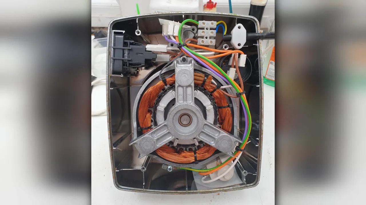
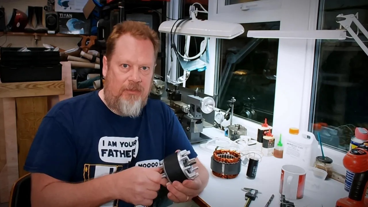
When our old Magimix food mixer finally went tango uniform, I had a look at the remains and thought it would be a perfect donor for this job.
Inside these mixers you tend to find a fairly substantial motor, and that’s exactly what I wanted. Once extracted from its impressively stubborn plastic housing, the useful bits were:
- The stator, which contains the windings
- The rotor, which normally spins inside it
I always used to mix those names up until I found an easy way to remember them:
- The rotor rotates
- The stator is stationary
For this project, the stator is the interesting bit. That’s the coil assembly. The rotor won’t be needed in normal operation because I’m not trying to make a motor run. I’m trying to make a tool demagnetizer by using the stator winding as an AC magnetic field source.
How the Demagnetising Bit Works
With mains AC applied to the stator winding, the coil produces an alternating magnetic field.
If a magnetised tool is placed inside or near that field and then gradually withdrawn, the residual magnetism in the tool should be reduced or removed. That is the same basic principle used in commercial degaussers. There’s no mystery box involved really. It’s mostly just a coil and some common sense.
Well, common sense and a healthy respect for mains electricity.
Version One: The Rotating Magnet Contraption That Didn’t Really Work
Before the food mixer motor came along, I had already tried a first attempt at a demagnetiser.
Version one was a 3D printed cylinder with four holes in it, each holding a large neodymium magnet. The magnets were arranged in alternating polarity, north south north south, a bit like a revolver cylinder full of questionable decisions.
The idea was simple enough:
- Put the printed magnet holder into a drill
- Spin it up
- Create a changing magnetic field near the tool to be demagnetised
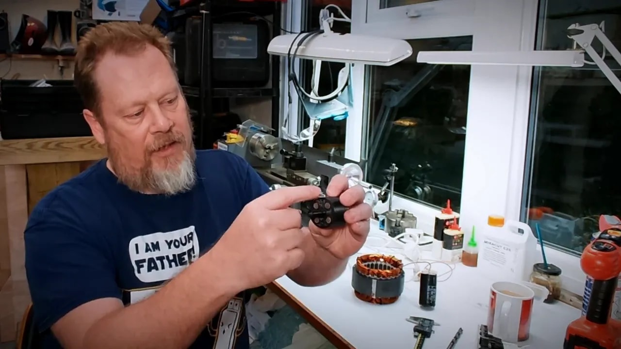
In theory, not entirely mad. In practice, it didn’t work very well.
I didn’t spend ages troubleshooting it, but it was clear enough that it wasn’t going to be the answer, so that idea was shelved until the deceased food mixer provided a much better route.
Understanding the Motor Before Rewiring It
If you’re going to make a tool demagnetizer from a salvaged motor, it helps to understand what sort of motor you’ve actually got.
This one is a single-phase induction motor designed to run from UK mains, so 240 V AC at 50 Hz.
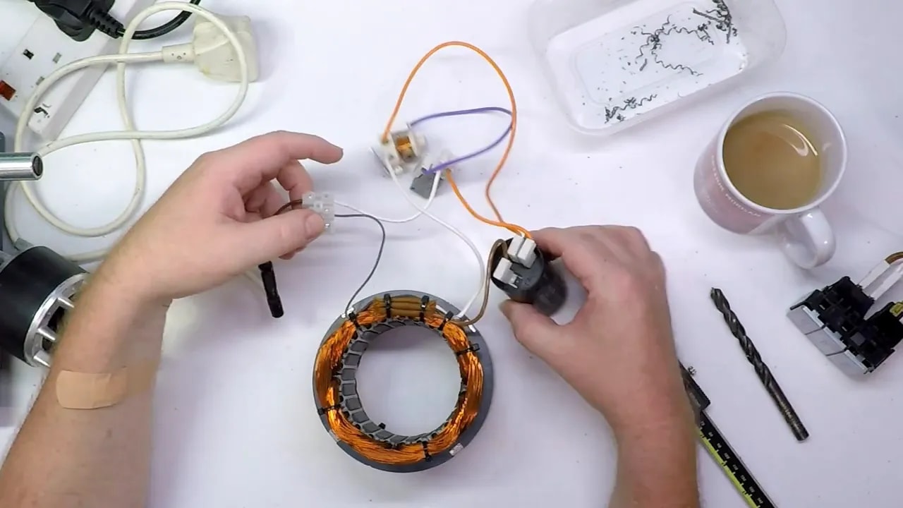
One thing that stands out immediately is that the motor has three wires coming from the stator, not two. That can look a bit odd if you’re expecting a simple live and neutral arrangement.
The reason is that a single-phase induction motor usually has:
- A run winding
- A start winding
- A common connection shared between them
In this case:
- Blue is the common, connected to neutral
- White is the run winding
- Brown is associated with the start winding via the capacitor
Why a Single-Phase Motor Needs a Start Winding
A single-phase induction motor is not inherently self-starting. If you energise only one winding, the rotor doesn’t know which way to go. It just sort of sits there and vibrates at mains frequency rather than properly getting going.
To overcome that, the motor uses:
- A second winding
- A capacitor in series with that winding
The capacitor shifts the phase of the current in the start winding. That phase shift creates the conditions for a sort of rotating magnetic field, which gives the rotor a kick in the right direction and gets the motor spinning.
Once the motor is up to speed, the start circuit is removed and the motor keeps running on the run winding alone.
The Original Mixer Control Circuit
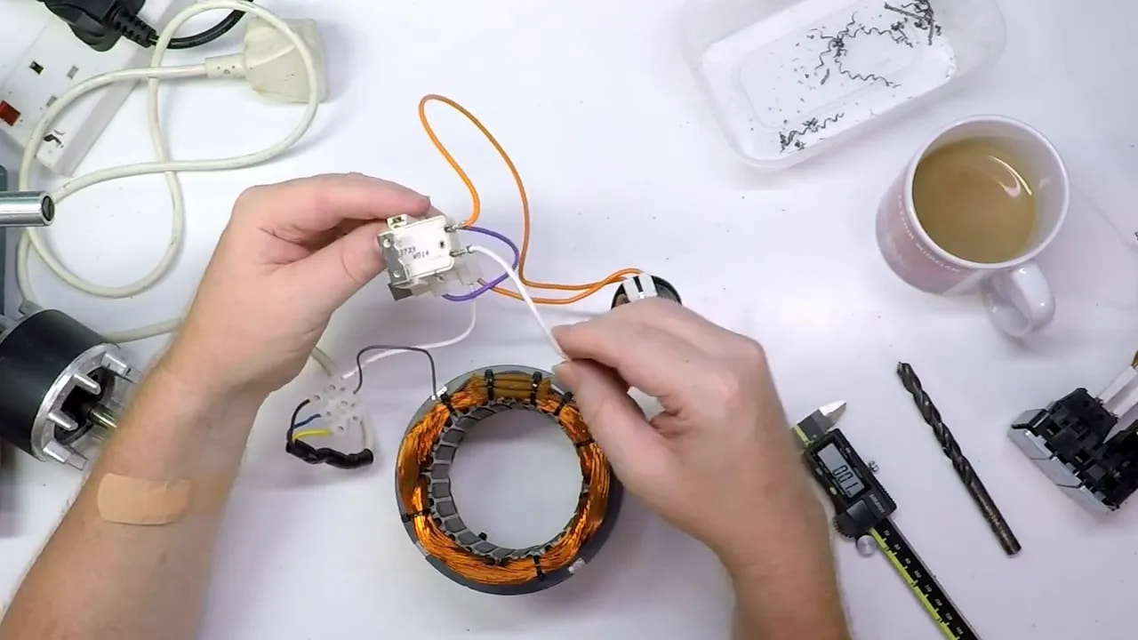
The food mixer originally had a selector switch and a safety interlock. The mains live fed through those controls before it reached the motor circuit.
There was also a current relay, which is quite a clever little device.
Here’s what it did:
- Mains power is applied.
- The run winding takes a high inrush current because the motor is stationary.
- That high current energises the relay.
- The relay connects the start winding and capacitor.
- The phase-shifted start winding gets the rotor moving.
- As the motor spins up, current drops.
- The relay drops out and disconnects the start winding circuit.
For a normal motor, that’s all very sensible.
For a demagnetiser, most of it is unnecessary. I only need the run winding to produce the alternating magnetic field. The start winding and all the original switching gubbins can effectively be left out of the final arrangement.
The Big Problem: Running the Stator Without the Rotor
This is where things get more interesting.
If you remove the rotor and simply apply mains power to the stator winding, the current draw can become excessive. The motor is no longer operating as a motor in the normal sense, and without the rotor interacting magnetically with the stator, the winding no longer has the same effective load.
A useful analogy is a car engine in neutral with the throttle held flat to the floor. It races away because there’s nothing sensible resisting it.
Likewise, a stator energised without the rotor in place can draw a lot of current, get hot very quickly, and potentially destroy itself.
That’s why many improvised degaussers made from motor stators are only used in short bursts. They work, but they heat up rapidly because the coil is effectively under far less restraint than it was in its original application.
I wanted something a bit better than that. If I’m going to make a tool demagnetizer, I’d rather not have it operating under a strict “several seconds before smoke” rule.
How to Limit the Current
The whole trick with this design is controlling the current through the run winding so the coil produces a useful magnetic field without trying to cook itself.
There are a few possible ways to do it.
Option 1: Electronic Current Limiting
One approach would be to build some form of electronic control circuit, perhaps with thyristors or something along those lines, to limit the current actively.
That would probably work, but it’s also more involved than I wanted for a practical workshop project. The point here is to repurpose a dead appliance, not build a whole new power electronics experiment.
Option 2: Put a Lamp in Series
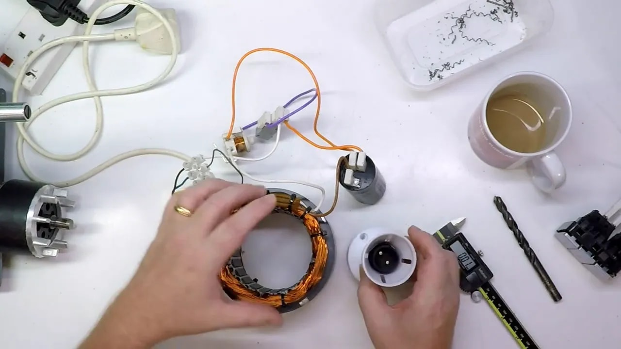
A very simple method is to wire a mains lamp in series with the stator winding.
That works because the bulb acts as a current-limiting element. If, for example, you put a 100 W lamp in series with the coil, the current available to the winding is limited by what can pass through the lamp.
That may well be enough for demagnetising tools, since this doesn’t need to power a small village. It only needs to create a useful alternating field.
It is crude, but crude and effective has a proud history in workshops.
Option 3: Use the Motor’s Existing Capacitor
The option I’m planning to try is a bit neater. Instead of using the start capacitor in the motor’s original start circuit, the idea is to put that capacitor in series with the incoming mains supply feeding the run winding.
In AC circuits, a capacitor presents capacitive reactance. In practical terms for this application, that means it resists current flow without behaving like a plain resistor.
The expectation from the calculations is that this arrangement should limit the current to around 3.5 amps, which is in the rough region of 700 to 750 watts.
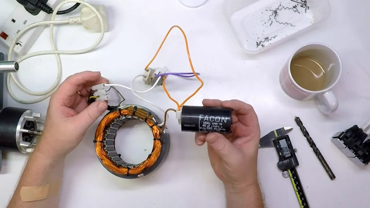
That sounds much more sensible. Enough field strength to be useful, hopefully, without turning the stator into a workshop hand warmer.
The Basic Plan for the Final Demagnetiser
So the intended setup is quite simple in principle:
- Use the motor stator as the demagnetising coil.
- Disconnect the start winding from the working circuit.
- Feed the run winding from mains.
- Limit current using the salvaged capacitor in series.
- Eventually house everything in a proper enclosure.
If all goes well, the finished unit should allow magnetised tools to be inserted into the centre of the stator and slowly withdrawn while the AC field does its work.
And if it works properly, the next step is to build a tidy 3D printed enclosure so the wiring is safe, insulated, and not just sat on the bench looking like an invitation to regret.
A Few Practical Notes Before You Try to Make a Tool Demagnetizer This Way
This sort of project involves mains electricity, which is perfectly capable of killing you. That is not drama, that is just fact.
If you’re thinking of doing something similar, a few points matter:
- Know exactly what motor type you’re dealing with.
- Identify the windings correctly before applying power.
- Do not energise a salvaged stator casually just to see what happens.
- Provide proper current limiting.
- Enclose all mains wiring safely before regular use.
Repurposing old machinery is great fun and often very useful, but mains-powered improvisation is only enjoyable if you keep all the excitement on the engineering side rather than the electrocution side.
Where This Project Stands
At this stage, the important groundwork is done.
The motor has been identified, the original wiring scheme has been understood, the unnecessary start circuitry has been separated from the useful parts, and there’s a working plan for how to make a tool demagnetizer that should be practical and reasonably civilised.
The next job is the one that always gets interesting: actually wiring it up, powering it, and finding out whether the theory behaves itself in real life.
With a bit of luck, that should result in a proper workshop demagnetiser and a rescue operation for my unfortunate calipers.