THE HARDWARE
Welcome to part two of the tutorial to make your own CS:GO C4 game prop! In this episode we’re going to be talking about and making the hardware for the prop.
This blog post is supplemental to the YouTube video below. For the full tutorial please check out the video and refer back here for the file downloads, parts list, additional information and also any corrections or additions that were highlighted after the video was released.
Any questions, please leave a comment below or in the comments of the video.
parts list
Here’s a list of the parts you will need to obtain. I have provided links to most of the items on eBay which is where I bought most of them.
- Arduino UNO
- Banana Test Leads – Black, Red, Yellow 4mm straight
- Missile Switch – Red Cover (LED doesn’t matter – not used)
- 4 x 3 Membrane Keypad
- 1601 16×1 Character LCD Display Module – Yellow Backlight
- WTV020-SD-16P MP3 Player Module with SD-Card Slot
- Miniature Speaker 27mm Diameter
- DS3231 Real Time Clock Module (RTC)
- PCF8574 8 Bit I2C GPIO Extender (Blue)
- 3A Mini DC-DC Step Down Converter 4.75-23V to 1.0-17V
- Floppy Disk Drive Data Ribbon Cable
- 0.25mm 30AWG Kynar Hookup Wire (Any colour)
- 16/0.2 20AWG Equipment Wire Red & Black (1m each)
- 0.1mm Vero Board 60mm x 50mm
- 1mm Vero Pins
- 50k Trimpot
- 150R 1/4W Resistor 2off
- Bi-colour Red/Green 5mm LED
- 9V Battery snap on connector
- M3 x 8 Countersunk Black Steel Pozi/Philips Head Screws 14off
- M3 x 8 Button Head Allen Screws
- Assorted Laptop Screws (if you don’t have any in your stash)
- 9V Battery (PP3, LR22, MN1604)
- 2Gb Micro SD Card – use whatever you can get your hands on for this
- USB-B PCB Mount Socket – (From Arduino – see info below)
- USB A-B Cable
- 2.5mm x 5.5mm Chassis Mount DC Jack Socket
- 9V 500mA DC Power Adapter with 2.5mm Jack Plug (Optional)
- 2 x white cable ties
- Silver Duck tape (Gaffa tape / Duct tape)
Some of the parts above are easy enough to get hold of such as batteries etc…
For the SD-Card, I used an old 2Gb card I had laying around in my man drawer. This was plenty large enough for the sound files for the project so no need for massive amounts of storage. Note that some devices work better with some SD Cards, so if you have problems getting the sounds to play it’s worth trying different SD Cards to see if you can find one that is more compatible. It’s all a bit of a lottery with some devices.
I have listed the main screws that were used in the list above, but again some of the smaller fasteners were raided from my stash of old laptop screws, so you will have to improvise for some of the screws that aren’t specifically listed.
USB-B PCB Mount Socket
We’re going to be covering the wiring and electronics in Part Three of this series. But in case you want to crack on with assembling the enclosure you will need to deal with the USB-B Socket, so we’ll skip ahead a little.
The USB-B Socket on the back of the prop was de-soldered from the Arduino and soldered onto a piece of Vero board so that it could be mounted in the rear of the prop.
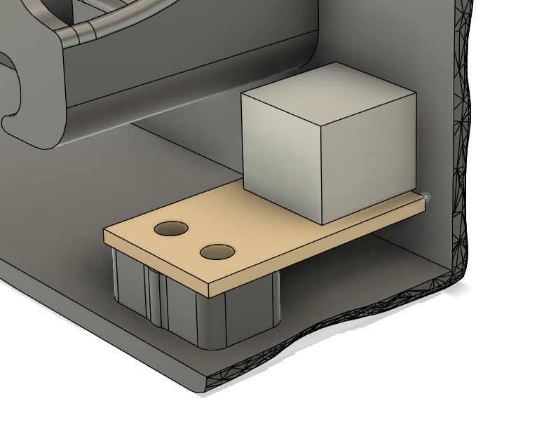
The dimensions for the vero board are shown below:
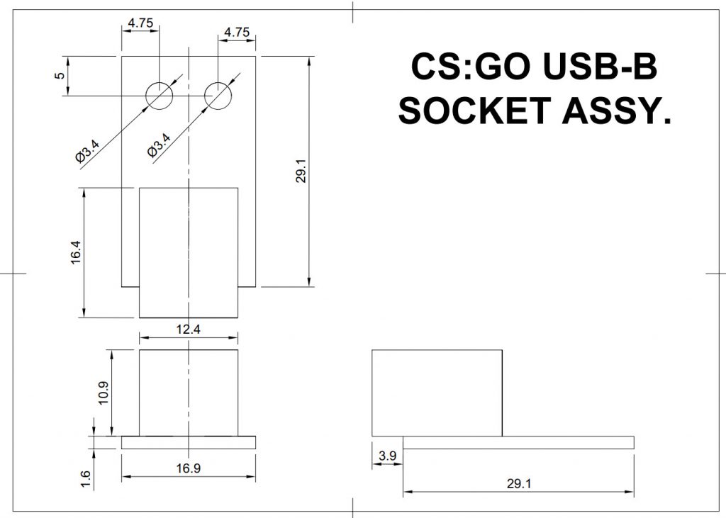
With the USB socket soldered to the Vero board, cut the tracks on the bottom of the Vero board to isolate each pin of the USB socket, and tack on (solder) a length of Kynar wire to each of the USB socket pins on the underside of the board.
When we come to wire it all up in part three, we will connect the wires from the USB socket to the corresponding holes on the Arduino. We are in effect just extending the Arduino USB socket to the rear of the device.
You will need to attach the wires to the USB socket before you glue on the rear panel as you won’t be able to gain access to it afterwards.
2.5mm DC Jack Socket
The DC Jack is a 2.5mm x 5.5mm chassis mount variety. In case you can’t get the one that I linked, I’ve created a drawing of the dimensions of the one I used so hopefully you can find one the same size.
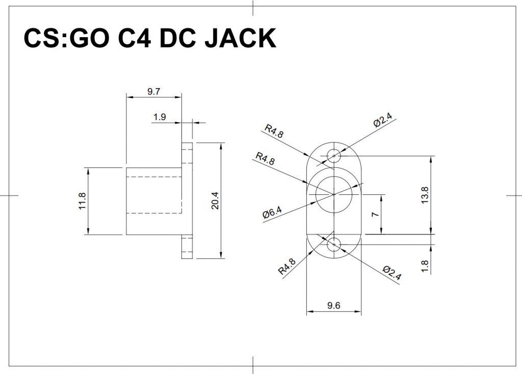
If you want to tweak the design in Fusion 360 to accept a different design of DC Jack, Patreon subscribers on the middle tier or higher have access to the original f3d file for the project.
Screw Threads
When I originally built this, some of the screws I bought and some of them were scrounged from my stash.
The main M3x8 countersunk screws that hold the front panel to the inner tray, that attach the rear door and the USB standoff are listed in the parts list above. As are the M3x8 Button Cap screws that attach the keypad.
For the other smaller screws you will need to improvise these as you go so I have included a link in the parts list to a seller that sells assorted laptop screws, as these are what I used for things like the speaker clamps and mounting the LCD display and internal circuit board.
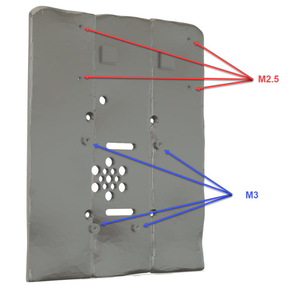
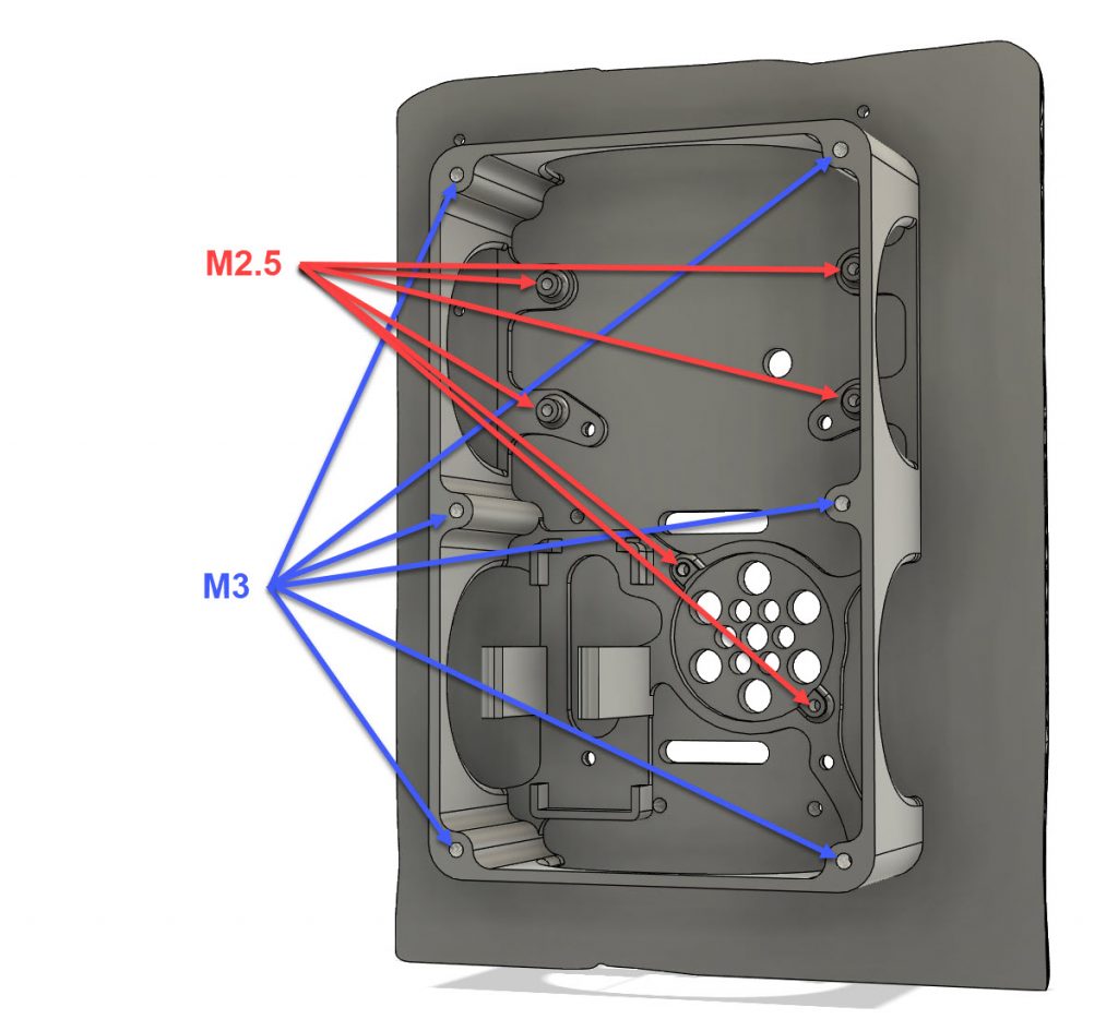
Some of the holes in the 3D printed parts are intended to be threaded. I recommend that for the M3 holes you tap these out using a tap and tap wrench. The M2.5 screws are OK just to screw straight into the parts without tapping. You don’t *have* to tap the M3 holes, you could probably let the screws cut their own threads, but at that size they have a greater chance of splitting the plastic if you don’t cut a thread first.
Here are some diagrams of the various thread sizes.
USB Board Standoff Thread Sizes
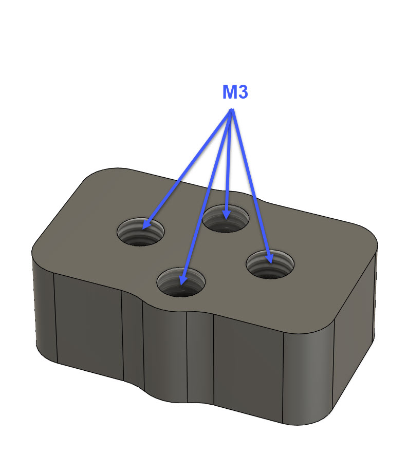
Front Panel Thread Sizes
Inner Tray Thread Sizes
The C4 Labels
For the C4 Labels I knocked up a design in Photoshop and printed the labels onto plain copy paper using an inkjet printer.
You can right click and download the label image below.
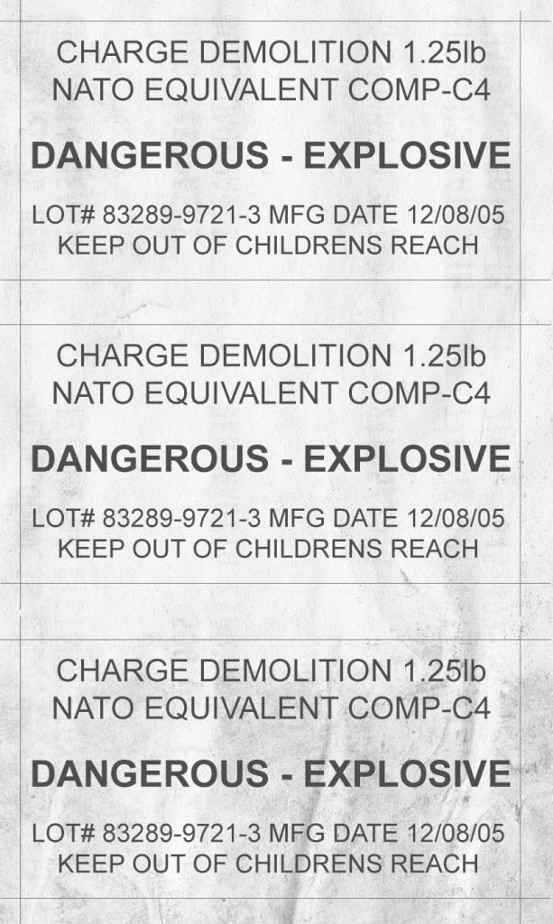
After the painting is finished it’s then just a case of cutting the labels out with scissors or a craft knife, tear up the edges a bit to give them some wear and glue them onto the C4 prop with PVA glue or similar.
After the labels were attached the whole thing got 3 or 4 coats of AK Ultra Matt acrylic varnish sprayed over it with an airbrush to seal it all in and give the labels some protection.
You don’t have to give it a final coat of matt varnish but doing so gives it a bit more scratch resistance and knocks down any gloss from the paint.
The 3D Models
Here’s an overview of all the 3D models for the build.
You can drag the models around using your mouse or touch screen.
Front
Top
Bottom
Left Side
Right Side
Rear Door
Rear
Inner Tray
DC Jack Spacer
USB Board Standoff
Speaker Clamp
Keypad Mount
Keypad Spacer
downloads
The files below are free to download and use, if you enjoy them and want to support the channel and help me to make more great content feel free to hit the “Buy me a Beer” links on the right or at the bottom of the page, or head over and join my Patreon.
Below you can download the files needed to print your own CS:GO C4 Game Prop…
CS:GO C4 3D Files (3.3Mb)
A ZIP file containing all the STL and 3mf files needed to 3D print the parts for this project.
The STL files are the raw 3D files you can pull into your favourite slicer.
The 3mf files are Cura Slicer project files so you can see how I setup each print job.



3 thoughts on “Make your own CS:GO C4 PROP – Part 2 – Hardware”
Hi sir,
Huge congrats for that great project !
Can you tell us how did you get that kind of organic texture with your triangle pattern on Fusion 360 ?
Thank you!
The triangle textures were a result of having exported the model to Blender for sculpting the edges and then re-importing to Fusion 360.
Thanks for the fast answer. Best of luck for your next projects !