
THE ELECTRONICS
Welcome to part three of the tutorial to make your own CS:GO C4 game prop! In this episode we’re going to be talking about and making the electronics and wiring for the prop.
This blog post is supplemental to the YouTube video below. For the full tutorial please check out the video and refer back here for the file downloads, parts list, additional information and also any corrections or additions that were highlighted after the video was released.
Any questions, please leave a comment below or in the comments of the video.
parts list
We covered the parts list in Part 2, but for your convenience here it is again.
I have provided links to most of the items on Amazon which is where I bought most of them.
- Arduino UNO
- Banana Test Leads – Black, Red, Yellow 4mm straight
- Missile Switch – Red Cover (LED doesn’t matter – not used)
- 4 x 3 Membrane Keypad
- 1601 16×1 Character LCD Display Module – Yellow Backlight
- WTV020-SD-16P MP3 Player Module with SD-Card Slot
- Miniature Speaker 27mm Diameter
- DS3231 Real Time Clock Module (RTC)
- PCF8574 8 Bit I2C GPIO Extender (Blue)
- 3A Mini DC-DC Step Down Converter 4.75-23V to 1.0-17V
- Floppy Disk Drive Data Ribbon Cable
- 0.25mm 30AWG Kynar Hookup Wire (Any colour)
- 16/0.2 20AWG Equipment Wire Red & Black (1m each)
- 0.1mm Vero Board 60mm x 50mm
- 1mm Vero Pins
- 50k Trimpot
- 150R 1/4W Resistor 2off
- Bi-colour Red/Green 5mm LED
- 9V Battery snap on connector
- M3 x 8 Countersunk Black Steel Pozi/Philips Head Screws 14off
- M3 x 8 Button Head Allen Screws
- Assorted Laptop Screws (if you don’t have any in your stash)
- 9V Battery (PP3, LR22, MN1604)
- 2Gb Micro SD Card – use whatever you can get your hands on for this
- USB-B PCB Mount Socket – (From Arduino – see info below)
- USB A-B Cable
- 2.5mm x 5.5mm Chassis Mount DC Jack Socket
- 9V 500mA DC Power Adapter with 2.5mm Jack Plug (Optional)
- 2 x white cable ties
- Silver Duck tape (Gaffa tape / Duct tape)
Some of the parts above are easy enough to get hold of such as batteries etc…
For the SD-Card, I used an old 2Gb card I had laying around in my man drawer. This was plenty large enough for the sound files for the project so no need for massive amounts of storage. Note that some devices work better with some SD Cards, so if you have problems getting the sounds to play it’s worth trying different SD Cards to see if you can find one that is more compatible. It’s all a bit of a lottery with some devices.
I have listed the main screws that were used in the list above, but again some of the smaller fasteners were raided from my stash of old laptop screws, so you will have to improvise for some of the screws that aren’t specifically listed.
BLOCK DIAGRAM
Here’s an overview of the main electronic components, we will discuss each of them and their roles in turn before going on to discuss how it is all connected together referring to a wiring schedule.
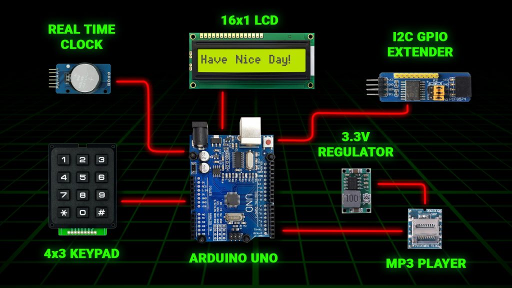
ARDUINO UNO
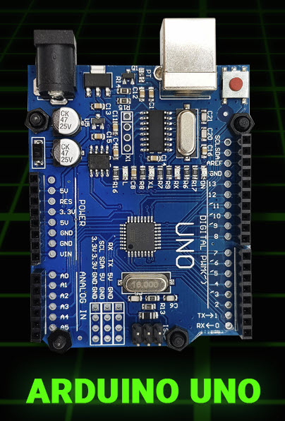
The brains of the operation.
The Arduino is a single board computer that controls all of the functions of the C4 Prop. As you can see in the main block diagram, everything connects back to the Ardunio either feeding information into it or receiving commands from it.
The Arduino series of single board computers are my favourites for this type of project as they have tons of I/O (Input / Output) built in, the programming language is very close to the hardware and they are very cheap.
So what do I mean when I say that the programming language is very close to the hardware? Well with the Arduino the programming language has built in commands to talk directly to I/O pins on the device making it very simple to communicate with external devices. By contrast a Raspberry PI is really a single board PC, and as such the operating system is far more complex making it more difficult to program and use I/O. The PI also has less native I/O so you’d need to add on I/O modules or extenders to match the I/O capabilities of the Arduino.
Don’t get me wrong the PI is an awesome device, but for this kind of application it’s too powerful and the simplicity and built in I/O capabilities of the Arduino makes it a better choice in this scenario.
16×1 LCD DISPLAY
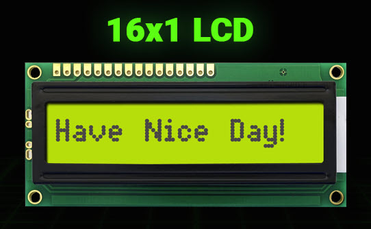
The 16×1 LCD Display is so named because it has 1 line of text which can comprise of 16 characters.
These come in a variety of colours and line counts, the one you will need for this project is one line, 16 characters, yellow with a back light.
We will cover which pin of the LCD connects to which pin of the Arduino later in the wiring schedule, for most of the connections you don’t need to worry about what the pin does, just know that when you connect the correct pin of the LCD to the correct pin of the Arduino, the LCD software library will make sure that the LCD display gets sent the correct signals to make it work.
There are however a couple of connections that are worth mentioning.
LCD Brightness
The CS:GO C4 Prop doubles up as a clock when it’s not being used. It was intended to be used as a bedside clock and for that reason we don’t want the LCD backlight to be at full brightness during the night. We want the LCD to automatically dim at a certain time of the day and to go back to full brightness in the morning.
We handle this by making the brightness of the prop configurable, along with a setting for the time of day that the display should go dim and when it should go bright again. We will cover that functionality in more detail in part 4 when we discuss the software.
To control the brightness, we use an analogue output pin from the Arduino to connect to the backlight power supply pin of the LCD (Pin 15). The Arduino output is a PWM output (Pulse Width Modulation) which allows us to vary the amount of power that we put out on the pin, and therefore vary the brightness.
LCD Contrast
When I was building this device, I had a lot of trouble getting the LCD to display anything. I would send characters to the LCD but nothing would appear. It turned out that the reason was I hadn’t connected up the contrast pin of the LCD (Pin 3) thinking that I didn’t need it because I didn’t want to control the display contrast.
It turns out that unless you connect Pin 3 of the LCD to a 0-5V signal, the display will not display anything. So if you hit a similar problem, make sure you are feeding the contrast pin a suitable signal.
To do this all we need to do is connect each end of a 50k trimpot to 0V and +5V, and then feed the wiper of the trimpot to pin 3 of the LCD.
You can then adjust the trimpot to get the desired contrast on the display.
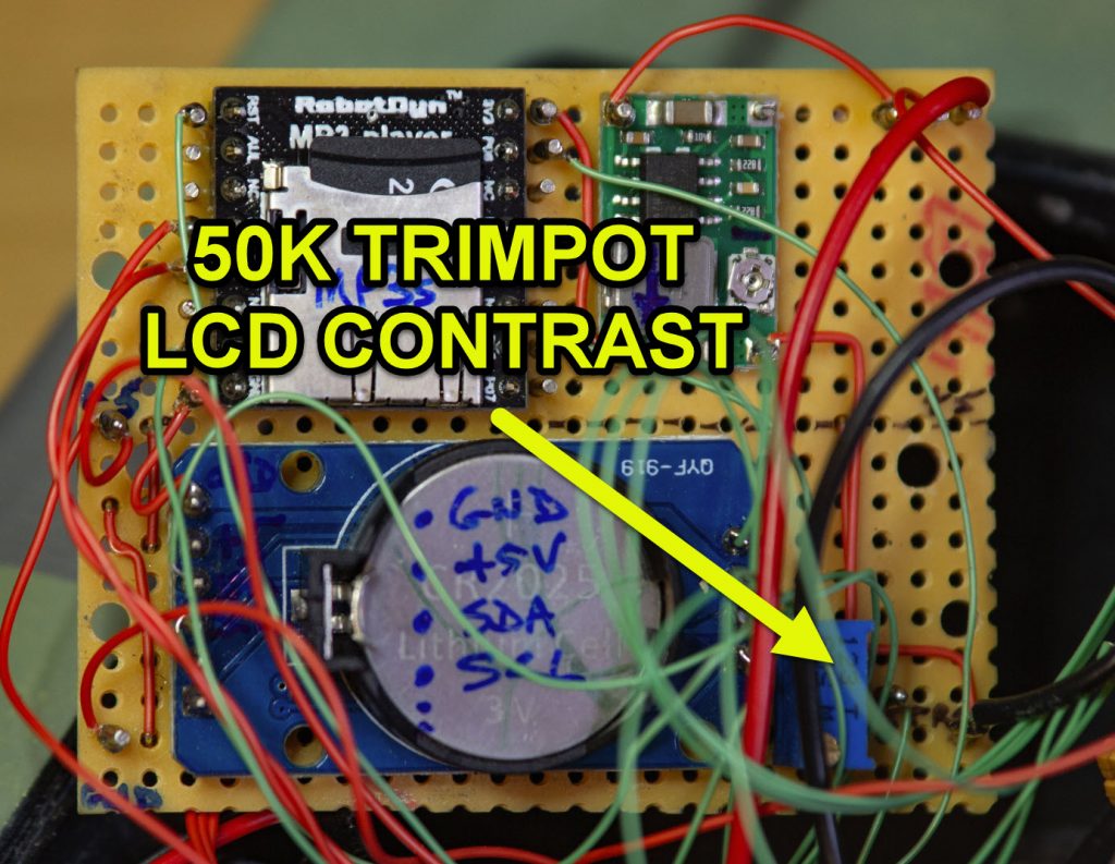
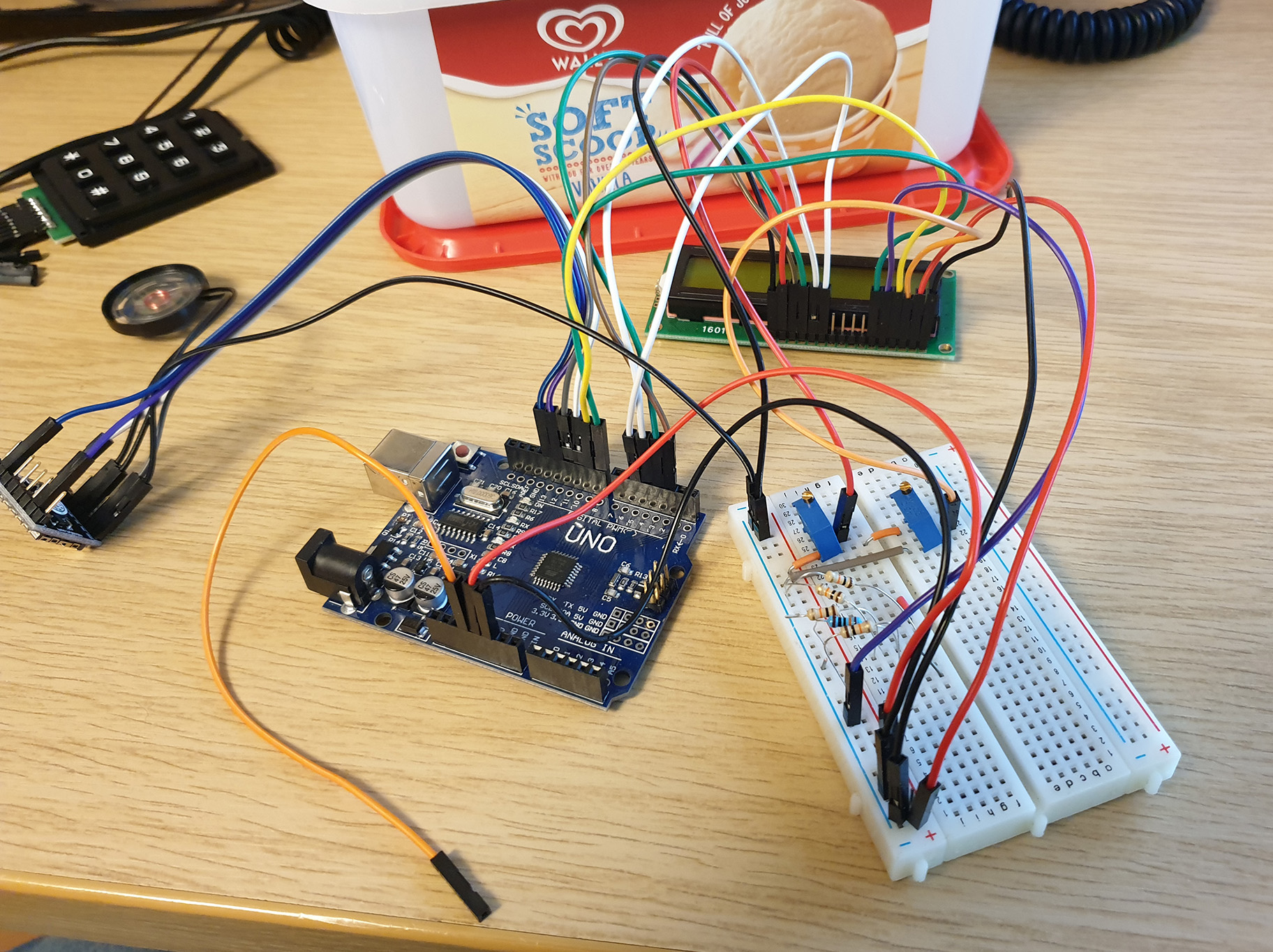
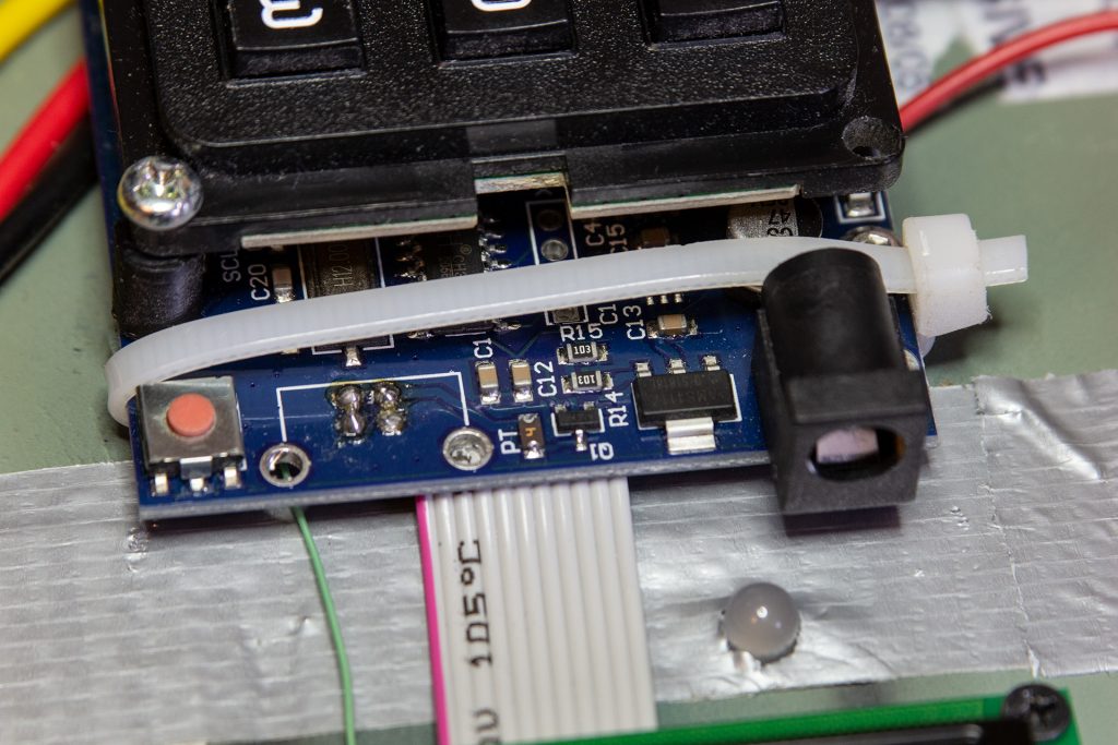
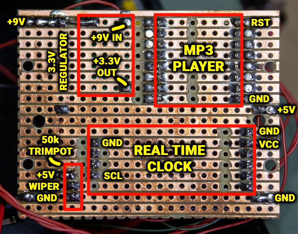
Later in this article we’re going to make a circuit board that will be home to many of the electronic components that make up the CS:GO C4 Prop, the trimpot is mounted on this board as can be seen in the photo above.
The wiring for the LCD display is via a length of floppy disk cable. This was chosen as it looks similar to what can be seen in the in-game C4.
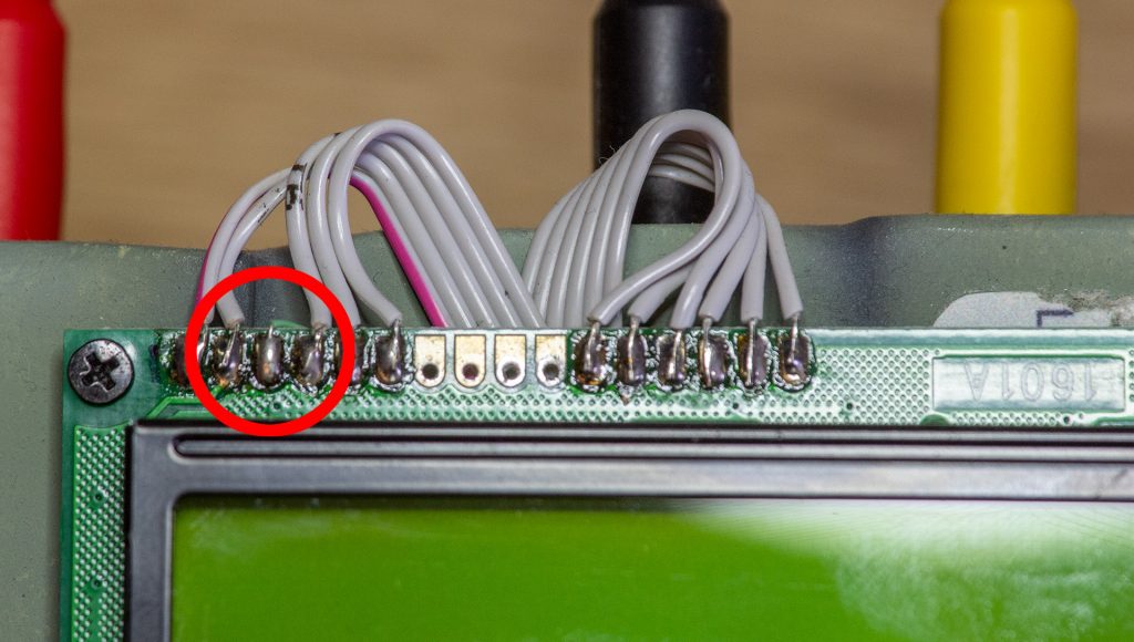
Note the third terminal is connected using green Kynar wire instead of the floppy cable. I can’t remember exactly why I did this (I am writing this 18 months after I made it), but was probably because I wired in the contrast connection after I had already wired in the floppy cable. You could probably go ahead and wire the third terminal using the floppy cable as there is no real reason not to.
Here you can see the floppy disk cable from the LCD and how it feeds under the Arduino. Note the rogue green Kynar wire.
REAL TIME CLOCK
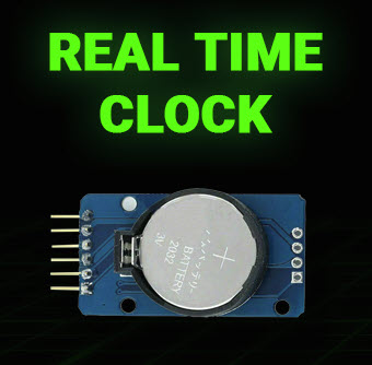
As mentioned before, the CS:GO C4 prop doubles as a bedside clock when not in use, and to keep the time we use an external DS3231 Real Time Clock module.
This module has a battery backed clock which means it will continue to keep accurate time even if the main CS:GO C4 battery goes dead and the prop is not powered from the external DC supply.
As with many electronic modules, we don’t need to understand all of the complexities of the device in order to be able to use it with an Arduino. All we need to do is connect the correct pins to the Arduino and the Real Time Clock software library will provide us with a simple means of talking to the device to set and read the time.
The DS3231 features two built in alarms, and it was my original intention to make the C4 Prop an alarm clock. Unfortunately I ran out of time when building it and so didn’t get around to implementing an alarm clock. It would make an interesting project for you to extend the functionality of this device to have an alarm clock function. Imagine waking up to hear “Bomb has been planted”.
4×3 KEYPAD
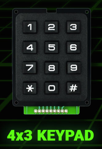
The 4×3 Keypad mimics the design of the in-game prop pretty closely, if you can find one with white keys so much the better however the black one does the job nicely.
The interfacing of this took a bit of working out as it is pretty unintuitive, however if you follow the wiring schedule and use the software that I provide in Part 4 you should be pretty much plug and play with this component.
If you need to know the pinout for the keypad it is as follows:
| Pin | Function |
|---|---|
| 0 | Not connected |
| 1 | Keypad Column 2 |
| 2 | Keypad Row 1 |
| 3 | Keypad Column 1 |
| 4 | Keypad Row 4 |
| 5 | Keypad Column 3 |
| 6 | Keypad Row 3 |
| 7 | Keypad Row 2 |
| 8 | Not connected |
Pin zero is the left most pin in the photo above, pin 8 is the rightmost.
One thing to be careful of when soldering to the keypad is that the copper tracks on the circuit board are very delicate and are easily dislodged. So don’t linger too long with the soldering iron or scrape them as they might flake off.
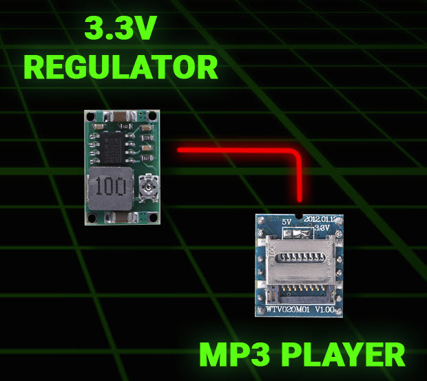
MP3 PLAYER
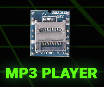
We call this WTV020-SD-16P device the “MP3 Player” whereas it actually isn’t an MP3 player, it’s an AD4 Player.
This device was probably the most problematic to get working with the CS:GO C4 prop, and it took ages to work out all its quirks and foibles.
The most difficult part was getting the audio format correct, and as mentioned you need to use .AD4 sound files to get one of these to work and not MP3s.
I will cover how you convert MP3 files to AD4 in part 4 when we talk about software, however there is another “gotcha” that you need to be aware of.
Since this device takes an SD Card, SD Cards operate on 3.3V and not the usual 5V that you would find in a circuit such as this. Whilst I was having trouble getting this device to work reliably I found out that you need to power it at 3.3V and not 5V as stated in some of the online tutorials I found for the WTV020-SD-16P.
For this I added an adjustable DC stepdown converter to provide the required 3.3V.
In terms of SD Cards, the WTV020-SD-16P was also quite fussy as to which SD Cards it would work with. I used an old 2Gb SD Card from my stash, it seemed that more modern and larger cards weren’t compatible. You might need to experiment a bit here.
If I were to build another CS:GO C4 prop I would probably not choose a WTV020-SD-16P again, and would investigate other options that allowed for direct playback of MP3 files. Feel free to experiment here.
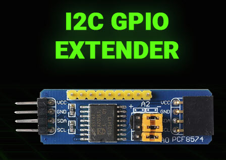
GPIO Extender
No matter how many I/O ports an Arduino comes with, I always seem to run out of ports before the end of a project. The CS:GO C4 prop was no exception.
I managed to get almost to the end of hooking everything up, and then for the final red/green LED that fits in the front panel I ran out of I/O.
No matter, the Arduino has an I2C bus which can be accessed via the SDA and SCL pins of the device. These are like a mini USB bus, that is a serial bus where you can connect multiple devices using only two data pins. In fact the Real Time Clock Module that we mentioned earlier is accessed via the I2C bus.
The PCF8574 provides an additional 8 digital I/O pins and is a handy and cheap way to add more I/O to the Arduino if you run out of pins. You can connect up to 8 of these devices which would give you an extra 64 digital I/O pins if required.
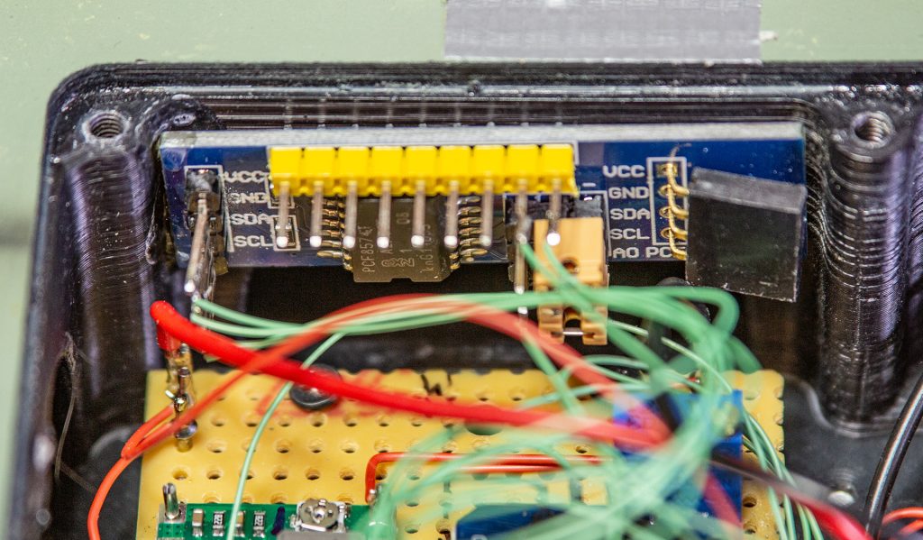
Because the GPIO Extender was an afterthought for the project after I ran out of I/O it was simply fixed to the side of the prop using a couple of dabs of super glue:
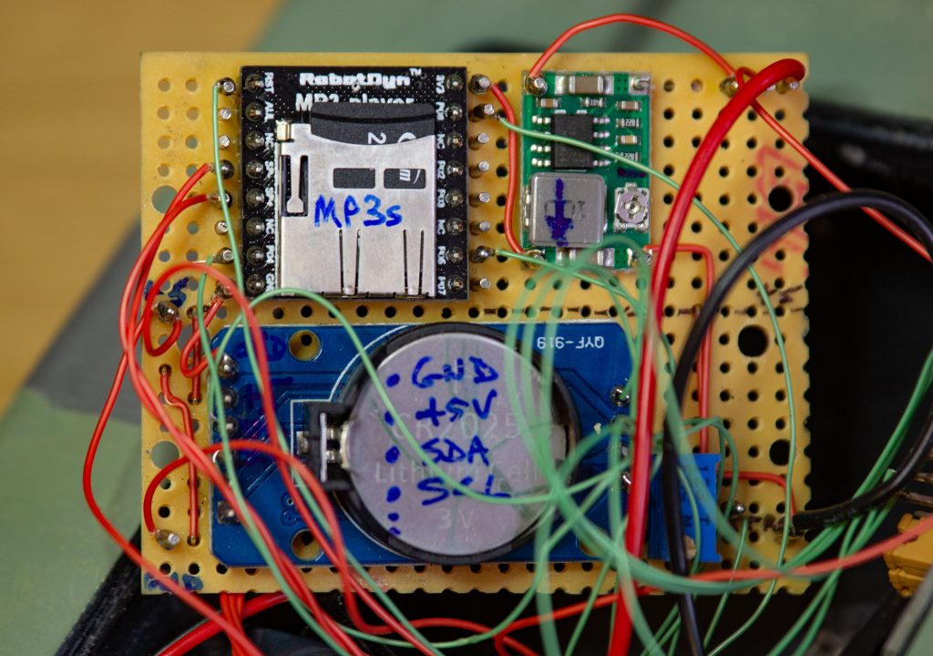
MAKING THE CIRCUIT BOARD
The MP3 Player, 3.3V Regulator, Real Time Clock and LCD Trimpot are all mounted on a circuit board made from Vero Board.
Vero board is a convenient way to quickly make up a circuit board without the need to design a Printed Circuit Board (PCB) and etch it yourself or pay to have one made for you. All you need to do is cut the Vero Board to size using a series of cuts with a sharp blade or a junior hacksaw, and then cut the copper tracks on the rear of the board where necessary.
Below you can see which tracks I cut to make the circuit board for the CS:GO C4 Prop. The easiest way to cut the tracks is with a 3mm or 1/8″ drill bit, put the tip of the drill in the hole where you want to cut the track and drill away the copper by twisting the drill bit back and forth with your fingers. Alternatively you can use a sharp blade to cut the tracks, but this is more difficult as it’s easy to leave a hair of copper behind that can bridge the gap and create a short circuit.
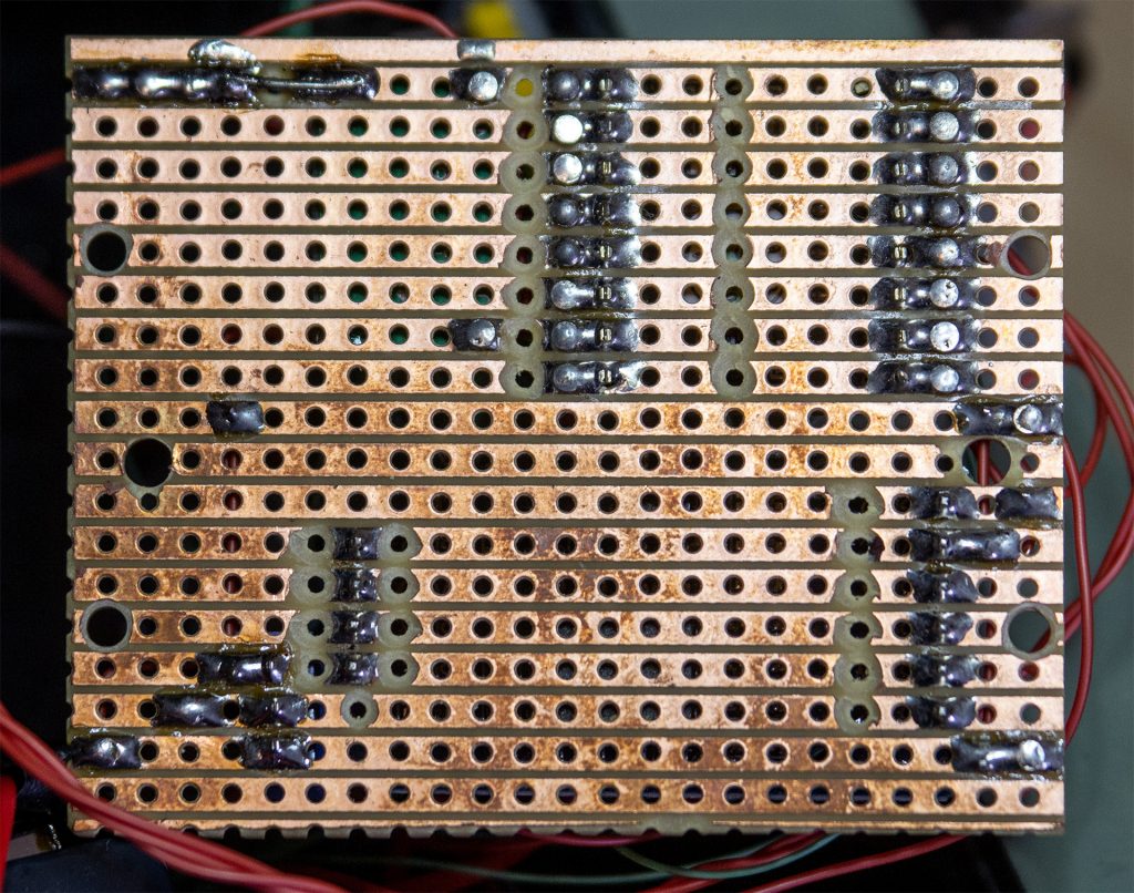
Where you need to attach a wire to the top side of the board, simply push a Vero Pin through from the underside of the board and solder it in place.
The photo below shows the rear view of the Vero board with annotations to show where the components are mounted and their orientations. This will help you to locate the components in the correct location and orientation.
There is a special configuration for the 3.3V Regulator.
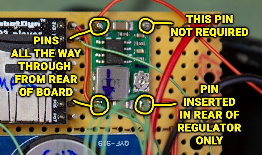
The regulator is only attached to the circuit board by the two pins on the left labelled “PINS ALL THE WAY THROUGH FROM REAR OF BOARD”. These two pins are soldered into the back of the circuit board and the regulator is located onto the pins and soldered in place.
The top right pin labelled “THIS PIN NOT REQUIRED” is not required, you can leave this out. The reason is this pin is a ground pin and is electrically common with the lower right ground pin. We only need to ground one ground pin and not both. I soldered a pin into the regulator but later realised it wasn’t needed.
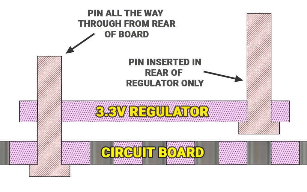
The lower right pin labelled “PIN INSERTED IN REAR OF REGULATOR ONLY” is a special case, this pin is inserted into the rear of the regulator and NOT the rear of the circuit board. Solder this pin into the regulator, and then fit the regulator onto the circuit board.
Here’s a diagram of what I mean:
Always remember, this is just the way I made the CS:GO C4 Prop – you can make it however you like so if you see something here that can be changed or improved upon, go for it!
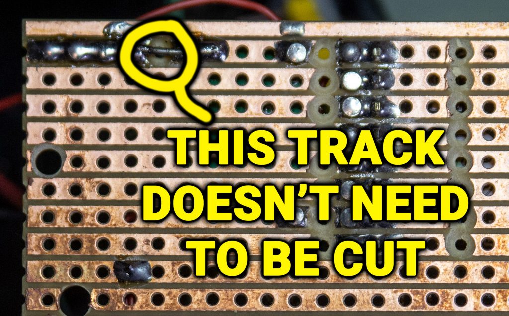
Also note there is a track on the rear of the board that has been cut and then bridged with a bit of wire. This track does not need to be cut. When I was making the circuit board I cut the track and then realised I didn’t need to.
RED/GREEN LED
On the front of the device is a bi-colour Red/Green LED.
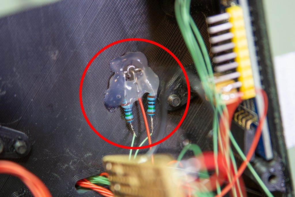
The LED has 3 legs, Red, Common and Green. For this I simply pushed the LED into the hole in the front panel, attached a couple of 150R resistors to limit the current to the LED and fixed it in place with a dab of hot glue.
SPEAKER
The speaker is held in place with two 3D printed tabs.
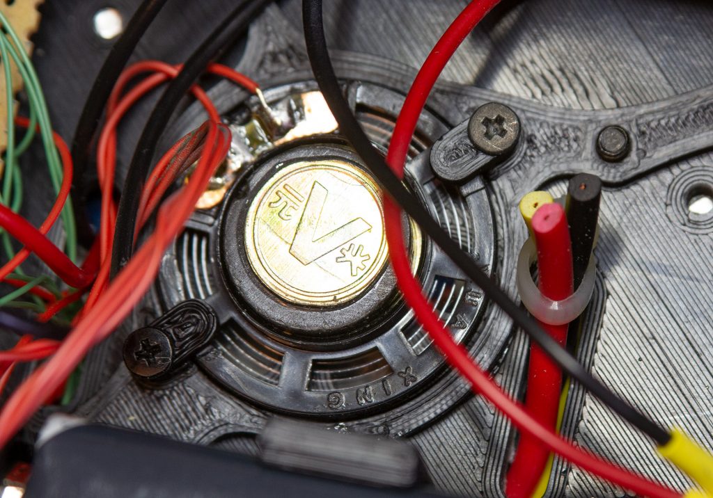
Note the leads from the banana plugs that have been fed through a slot in the front panel, a cable tie has been used to prevent the leads pulling back out through the slot, and the leads cut off as they are purely cosmetic.
THE MISSILE SWITCH
The device is powered on and off via the missile switch on the side.
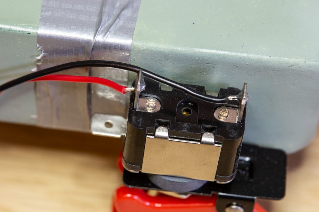
Note that the wires are simply soldered to the switch and there is no insulation on the wires. This is perfectly safe as there is only ever 9V DC on the contacts and there is no risk of shock from them.
DC JACK & BATTERY
The DC Jack and battery are interconnected so that with no DC jack inserted in the socket, the device will take its power from an internal 9V battery. When the DC Jack is inserted, the battery gets automatically disconnected and the device runs off the DC Jack Power input.
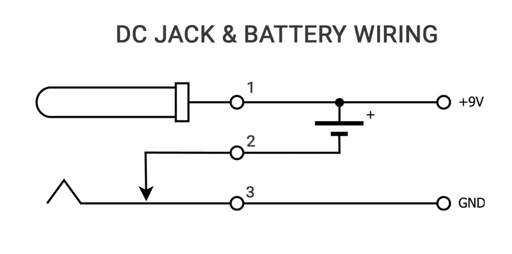
In the above diagram Pin 1 is the centre pin of the DC Jack and carries the positive supply.
Pin 3 is the ground or common connection.
Pin 2 is the special switched connector on the DC jack which is shorted to ground when the DC Jack plug is not present, and is open circuit when the DC Jack Plug is inserted. Inserting the DC Jack disconnects the negative or ground side of the battery, removing the DC Jack connects the ground side of the battery.
WIRING IT ALL UP
So I guess you’re itching to get wiring, but before we get to that there are a few things to mention.
I made this C4 Prop about 18 months before I wrote this blog, and back then I didn’t intend to create a YouTube “How to Build” series about it or to write a blog about how it was made. So some of the wiring might appear a bit scruffy and random. This is perfectly fine from an electronics point of view and doesn’t affect the functionality in any way, it just looks a bit untidy. If you wanted to do a tidier wiring job – go ahead and take your time.
There is no real colour code to the wiring. In some places I have used red wires for ground wires and in some places I used black wires. This really depended on what I had lying about at the time. Colour coding of wires is not that important as long as the wires go to the correct place. Back when I was a professional wireman, most of the wiring we did for military equipment was all done with pink wire. Rather than have colour coded wires we relied on having colour coded plastic sleeves on the ends of the wires or “idents” as we called them.
Where is the circuit diagram?
Another point about wiring is that wiring is rarely done from a circuit diagram. A circuit diagram is mainly used by service engineers to understand the electronics and how it works, it doesn’t really tell you how to go about wiring something. For wiring a Wiring Schedule is much more useful as it is basically a spreadsheet telling you which wire goes from which pin to which other pin.
All you need to do is pick a particular component, determine how many wires come from that component and cut the appropriate number of wires long enough to reach their destinations plus a bit of spare. Solder the wires to the pins of the component and then label the other ends with the wire number – a bit of masking tape works fine. Then you can run the wires to where they go and then solder them at their destination.
Keep going until you have installed all the wires on the schedule.
THE WIRING SCHEDULE
| Wire # | From | To | Comments |
|---|---|---|---|
| 1 | Arduino D0 | Keypad Pin 7 | Keypad Row 2 (Floppy Disk Cable) |
| 2 | Arduino D1 | Keypad Pin 5 | Keypad Col 3 (Floppy Disk Cable) |
| 3 | Arduino D2 | Keypad Pin 6 | Keypad Row 3 (Floppy Disk Cable) |
| 4 | Arduino D3 | LCD Pin 15 | LCD Back light +ve PWM (Floppy Disk Cable) |
| 5 | Arduino D4 | LCD Pin 4 | LCD RS (Floppy Disk Cable) |
| 6 | Arduino D5 | LCD Pin 6 | LCD EN (Floppy Disk Cable) |
| 7 | Arduino D6 | LCD Pin 11 | LCD Data 4 (Floppy Disk Cable) |
| 8 | Arduino D7 | LCD Pin 12 | LCD Data 5 (Floppy Disk Cable) |
| 9 | Arduino D8 | LCD Pin 13 | LCD Data 6 (Floppy Disk Cable) |
| 10 | Arduino D9 | LCD Pin 14 | LCD Data 7 (Floppy Disk Cable) |
| 11 | Arduino D10 | MP3 Pin 1 | MP3 Reset |
| 12 | Arduino D11 | MP3 Pin 7 | MP3 Clock P04 |
| 13 | Arduino D12 | MP3 Pin 10 | MP3 Data P05 |
| 14 | Arduino D13 | MP3 Pin 15 | MP3 Busy P06 |
| 15 | Arduino SDA | RTC SDA | Real Time Clock |
| 16 | Arduino SDA | GPIO Extender SDA | I2C GPIO Extender |
| 17 | Arduino SCL | RTC SCL | Real Time Clock |
| 18 | Arduino SCL | GPIO Extender SCL | I2C GPIO Extender |
| 19 | Arduino A0 | Keypad Pin 1 | Keypad Col 2 (Floppy Disk Cable) |
| 20 | Arduino A1 | Keypad Pin 2 | Keypad Row 1 (Floppy Disk Cable) |
| 21 | Arduino A2 | Keypad Pin 3 | Keypad Col 1 (Floppy Disk Cable) |
| 22 | Arduino A3 | Keypad Pin 4 | Keypad Row 4 (Floppy Disk Cable) |
| 23 | Arduino USB Pin 1 | USB Socket Pin 1 | Arduino USB Socket relocated to rear of device |
| 24 | Arduino USB Pin 2 | USB Socket Pin 2 | “ |
| 25 | Arduino USB Pin 3 | USB Socket Pin 3 | “ |
| 26 | Arduino USB Pin 4 | USB Socket Pin 4 | “ |
| 27 | Arduino +5V | Circuit Board +5V | +5V Supply from Arduino to Circuit Board |
| 28 | MP3 Pin 4 | Speaker + | |
| 29 | MP3 Pin 5 | Speaker – | |
| 30 | MP3 Pin 8 | Circuit Board Gnd | |
| 31 | MP3 Pin 16 | Regulator + Output | +3.3V From Regulator |
| 32 | RTC Gnd | Circuit Board Gnd | Real Time Clock |
| 33 | Regulator Gnd | Circuit Board Gnd | |
| 34 | 50k Trimpot Wiper | LCD Pin 3 | LCD Contrast |
| 35 | LCD Pin 1 | Circuit Board Gnd | LCD VSS (Gnd) |
| 36 | LCD Pin 2 | Circuit Board +5V | LCD VDD |
| 37 | LCD Pin 5 | Circuit Board Gnd | LCD R/W |
| 38 | LED Common | Circuit Board Gnd | Centre pin of Red/Green LED |
| 39 | LED Red Anode | GPIO P0 | Red anode pin of Red/Green LED |
| 40 | LED Green Anode | GPIO P1 | Green anode pin of Red/Green LED |
| 41 | RTC SDA | GPIO Extender SDA | GPIO Extender piggy backs of RTC Pins |
| 42 | RTC SCL | GPIO Extender SCL | “ |
| 43 | RTC Gnd | GPIO Extender Gnd | “ |
| 44 | RTC 5V | GPIO Extender 5V | “ |
| 45 | DC Jack Gnd | Circuit Board Gnd | DC Jack Pin 3 on DC Jack Wiring Diagram |
| 46 | DC Jack +9V | Missile Switch Pin 1 | DC Jack Pin 1 on DC Jack Wiring Diagram |
| 47 | Missile Switch Pin 2 | Circuit Board +9V | |
| 48 | Battery Clip -ve | DC Jack Switch Pin | DC Jack Pin 2 on DC Jack Wiring Diagram |
| 49 | Circuit Board +9V | Arduino VIN | |
| 50 | Circuit Board +9V | Regulator VIN | 3.3V Regulator + IN |
| 51 | LCD PIN 16 | Circuit Board Gnd | LCD Back light -ve |
Final Tips
Congratulations if you have managed to make it this far! Before I go here’s a few more tips for wiring the CS:GO C4 Prop:
When you are wiring to the Arduino, all I did was to tag (solder) the wires to the bottom of the Arduino straight onto where the Arduino header pins are soldered on.
Don’t worry about wire sizes. This device draws very little current so you will be able to use thin equipment wire throughout. I chose to use some thicker wires for the main incoming supply to the missile switch but this was mainly so that the wires look good and as they are external I wanted them to have some physical strength. For most of the internal wiring I used single core Kynar wire, this is more than adequate to carry the low currents present within this device.
Finally, have fun! If you find any errors in the information here comment below or leave a comment on the YouTube video and I’ll make corrections to this web page.