
Making a demagnetizer from a salvaged motor sounds delightfully simple right up until you remember that mains electricity and motor windings can turn a cheerful workshop project into a small electric heater in very short order. The basic idea works, but the trick is getting a strong alternating magnetic field without cooking the stator.
That is really what this whole exercise comes down to. If you strip a motor down and put full mains straight across the winding, it will pull a hefty current, get hot very quickly, and generally behave in a way that keeps the fire brigade interested. So the challenge in making a demagnetizer is not merely getting it to work. It is making it work safely and usefully.
Here I worked through the numbers, tried a few current limiting methods, checked the magnetic field shape, and then put the thing to work on a thoroughly magnetised drill bit.
The starting point
The donor for this bit of making a demagnetizer was the motor from an old food processor. Once stripped down, the stator winding gives a nice iron core and a ready made electromagnetic structure. The catch is that it was designed to run as a motor, not as a continuously energised degaussing coil.
With the rotor removed, the winding is left as a fairly low resistance inductive load. That means if you simply connect it to 240 volt mains at 50 hertz, it can draw far more current than is sensible for this application.
So before putting power on anything, it made sense to measure the winding properly and do a few sums.
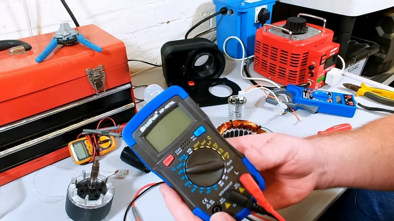
Measuring the winding
For making a demagnetizer like this, the two key values are:
- Resistance of the winding
- Inductance of the winding
The measured values came out at roughly:
- Resistance: 13.4 ohms
- Inductance: 38.2 millihenries
Because this is AC, resistance alone does not tell the whole story. The coil also has inductive reactance, which depends on frequency. At 50 hertz, the inductive reactance works out at about 11.93 ohms.
From there, the impedance of the winding is:
Z = √(R² + XL²)
Using the measured figures, the impedance comes out at roughly 17.94 ohms.
And that gives an expected current of:
I = V / Z = 240 / 17.94 ≈ 13.37 amps
That is quite a sobering number. It is right up near the limit of a UK mains plug fuse. In apparent power terms, you are in the region of over 3 kVA. For a small coil on a bench, that is asking for trouble.
Powering it carefully
Any time you are doing this sort of work, it is worth being rather boring about safety. Mains power is not forgiving.
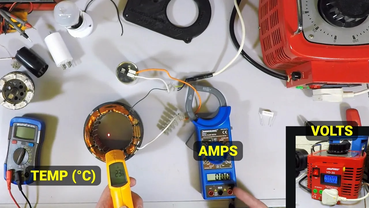
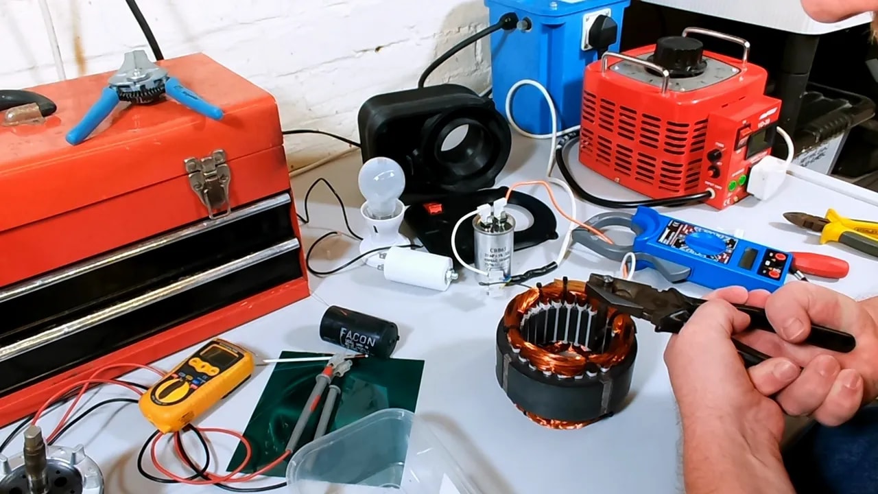
The setup used here had:
- An isolation transformer between the mains and the test setup
- A variac so the voltage could be wound up gradually from zero
- A clamp meter to measure current
- A temperature probe to keep an eye on the winding temperature
The point was not to slap 240 volts on and hope for the best. The point was to creep up on it and see what the real current looked like.
What happened with the bare winding
The voltage was increased to about 120 volts, roughly half mains, and the current came out at around 5.1 to 5.4 amps. Doubling that for a rough full voltage estimate suggests something like 10.2 amps in practice.
That is lower than the theoretical 13.37 amps, but still far too much for a useful demagnetizer that needs to remain on long enough to do a job properly.
The important bit was the heat. The winding temperature climbed rapidly into the 75 to 80 degree C region in a very short time. That told the story immediately. Yes, it works as an electromagnet. No, it is not yet suitable for making a demagnetizer you can use comfortably.
Why the rotor changes things
It is quite instructive to put the rotor back into the stator and repeat the test. With the rotor in place at the same 120 volt level, the current dropped to around 3.2 amps.
That is because the motor assembly behaves differently when the magnetic circuit is more complete. The rotor changes the effective impedance seen by the supply, so the coil does not just guzzle current in the same way as it does when left open.
For making a demagnetizer, though, the rotor is not what we want. The object being demagnetised needs access to the alternating field, so the open stator is still the useful geometry. But it is a good reminder that once you start dismantling a motor, the electrical behaviour changes significantly.
Could a resistor do the job?
In principle, yes. In practice, not elegantly.
You can limit current in an AC circuit with:
- Resistance
- Inductance
- Capacitance
Adding a large series inductor would be clumsy and bulky. Using a resistor would work, but because of the current involved, you would need something physically large and able to dissipate a fair old amount of heat.
A household incandescent bulb is basically a convenient power resistor, so a 100 watt lamp was tried in series with the winding.
The result was educational but not especially useful. The bulb limited the current so much that there was hardly any measurable current through the stator at all. With a more sensitive clamp meter arrangement using multiple turns through the clamp, the current worked out at only about 300 milliamps.
That is safe enough, but the magnetic field was feeble. If you need half a kilowatt of light bulbs just to demagnetise a tiny drill bit, the whole affair has gone a bit wrong.
Why a capacitor is the neat answer
For making a demagnetizer on mains AC, a series capacitor is a much tidier way to limit current. Unlike a resistor, it limits current by reactance rather than by burning energy off as heat.
So the next arrangement was:
- Live supply
- Capacitor in series
- Stator winding
- Neutral
With a 25 microfarad capacitor, the capacitive reactance at 50 hertz works out at about 127.38 ohms.
Now the total impedance becomes:
Z = √(R² + (XL – XC)²)
Using the measured and calculated values, the total impedance comes out at about 116.22 ohms, which predicts a current of roughly 2.06 amps at 240 volts.
That is much more sensible. Strong enough to generate a useful field, but not so fierce that the winding immediately turns into a toaster element.
Real world test with the capacitor
Once the capacitor was connected in series, the voltage was brought up to full mains. The actual measured current was around 1.7 amps, a bit lower than the predicted 2 amps, but near enough to show the approach was sound.
More importantly, the temperature behaviour was vastly better. The stator only crept up into the high twenties or low thirties in degrees C during the test. Compared with the bare winding, it was much more civilised.
There was also a clearly stronger magnetic effect than with the lamp test. A screwdriver offered to the core gave a definite buzz and pull, which is exactly the sort of thing you want when making a demagnetizer.
Start capacitor or run capacitor?
This bit matters.
The original motor came with a start capacitor, and naturally it seemed tempting to reuse it. In theory, because the demagnetizer would only be used for short bursts, that might have been acceptable.
In practice, the old original capacitor started getting hot. Very hot. It swelled, bowed, and generally looked as though it had had enough of life. That may have been partly because it was already tired, but it served as a very useful warning.
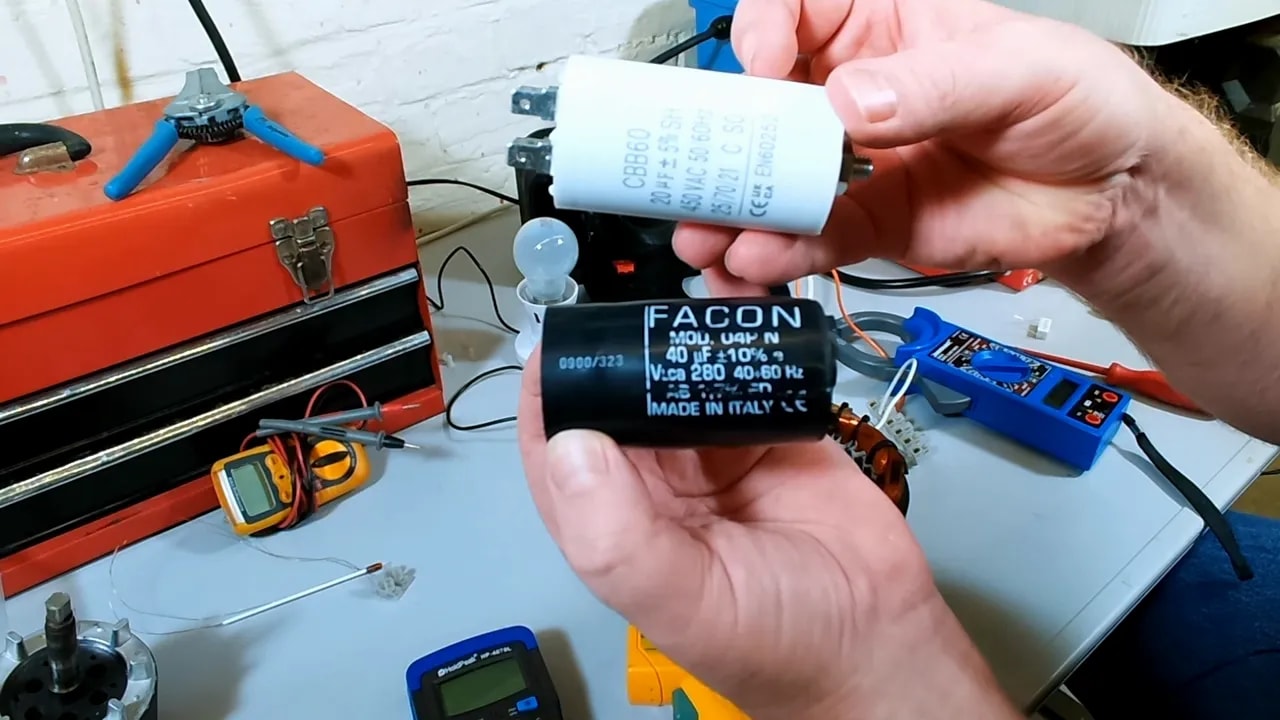
A run capacitor is the better choice for this job because it is designed for continuous duty. They are not ruinously expensive, and using the correct component avoids unpleasant surprises.
So if you are serious about making a demagnetizer this way, a run capacitor is the sensible route.
Finding where the magnetic field is strongest
One of the easy assumptions to make is that the best place to put the thing you want to demagnetise must be in the centre hole of the stator. It looks tidy, so it feels right.
But magnetic fields are under no obligation to behave according to what looks tidy on the bench.
To get a better idea of the field shape, two simple methods were used:
- Magnetic viewing film
- A homemade sensing coil connected to a sensitive meter
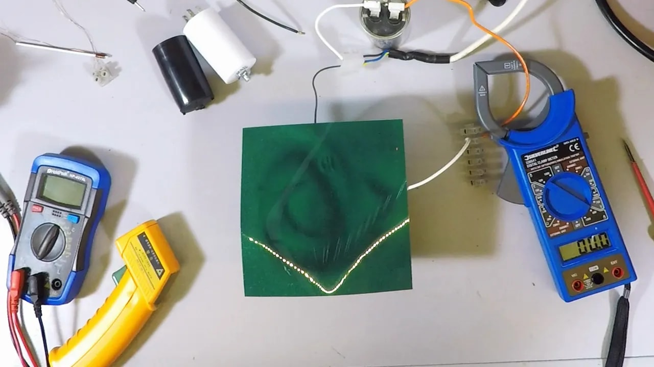
The viewing film showed the field pattern around the stator poles, which was fascinating in itself. The strongest visible features were not necessarily in the middle of the bore. They lined up more with the winding positions.
The little probe coil confirmed that the strongest alternating field was found close to the main windings, not in the middle. That distinction matters. For degaussing, you need an alternating field. A static pole is no good and can simply magnetise the object further.
So the useful lesson for making a demagnetizer is this:
- Do not assume the centre is best
- Test where the alternating field is strongest
- Mark those positions on the enclosure so you know where to offer the workpiece
How degaussing actually works
Demagnetising is not just a matter of sticking a part near a magnet and hoping for the best. The process relies on an alternating magnetic field that gradually reduces in strength.
The alternating field keeps flipping the magnetic domains back and forth. As the field strength falls away, those domains settle in a more random state, leaving the object with little or no net magnetism.
That is why the usual technique is:
- Place the item in the strongest alternating field
- Keep the AC field energised
- Slowly move the item away from the field
- Only then switch off
If you simply switch the field off while the item is still hard up against the pole, you may not get a proper degaussing effect.
Testing the finished setup on a drill bit
The first proper test item was a drill bit that had been sitting next to a strong permanent magnet and had become thoroughly magnetic. It would happily pick up steel swarf, which is exactly the sort of nuisance that makes a drill bit feel grubby and irritating in use.
The bit was held with pliers, placed right into the strongest field area near the winding, then gradually withdrawn away from the energised stator over a decent distance.
After that treatment, the result was obvious. The drill bit no longer held onto the steel chips. Job done. A proper success, and very satisfying in that quietly workshop sort of way.
What this project proves
Making a demagnetizer from a scrap motor is entirely feasible, but the important bit is understanding that the winding must be tamed. The raw stator on full mains is far too hungry. With some sensible measurement, a bit of AC theory, and a series capacitor chosen with care, it becomes a practical tool rather than a brief heating demonstration.
The main takeaways were these:
- The stripped stator winding had low enough impedance to draw a very large current on mains
- A simple resistor approach works poorly and wastes energy
- A series capacitor is a much neater current limiter for this sort of AC setup
- A run capacitor is preferable to an elderly start capacitor
- The strongest useful alternating field is near the main windings, not necessarily in the middle
- Proper degaussing needs a reducing alternating field, so the item must be withdrawn gradually
A few final workshop thoughts
I rather like projects like this because they sit in that nice middle ground between practical workshop problem solving and a bit of old fashioned bench experimentation. You start with a scrap appliance motor, do some sums, poke it with meters, and end up with a genuinely useful tool.
And that, to me, is the charm of making a demagnetizer. It is not merely an electronics exercise. It solves an annoying real workshop problem using something that might otherwise have gone in the bin.
Just remember the usual rule with mains powered contraptions in the shed: if in doubt, stop, measure it again, and keep your fingers where they belong.