
Captains (BUILD) log, star date 17th November 2013…
Ok I’m not a captain but the date is correct and here goes with my build log for the USS Enterprise…
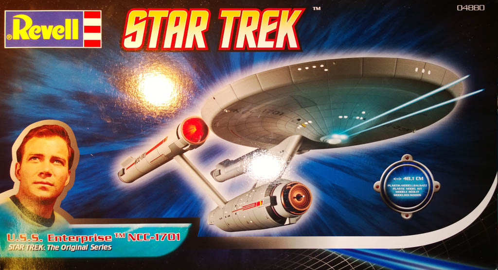
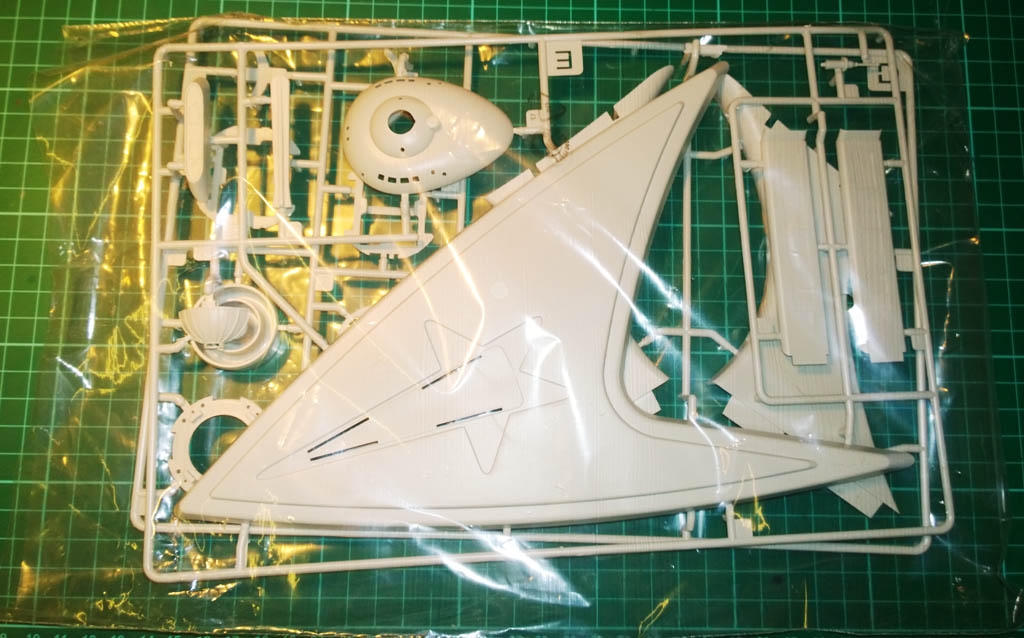
I’ve never built Sci-Fi stuff before but my wife is a big fan of the original Star Trek so I’m building her the original USS Enterprise as an early Xmas present. Not sure which Xmas it will be early for though 🙂
I’m going to be illuminating this one, not sure exactly how far I’m going to go with the engine lights as it’s still early days in the planning.
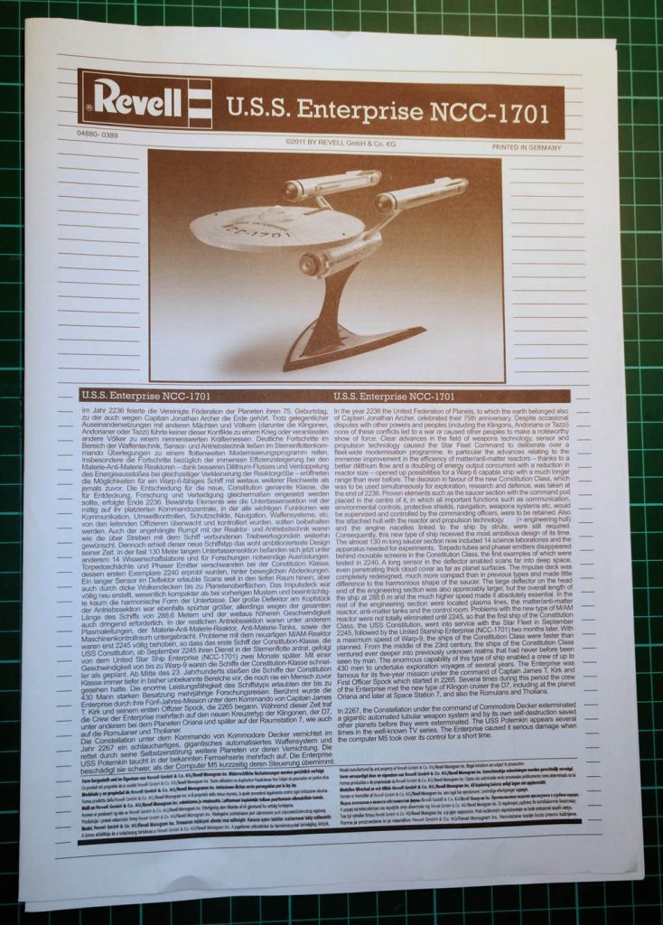
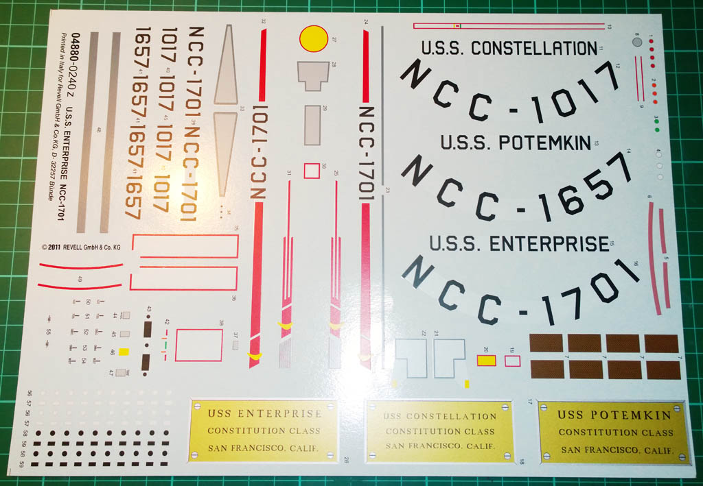
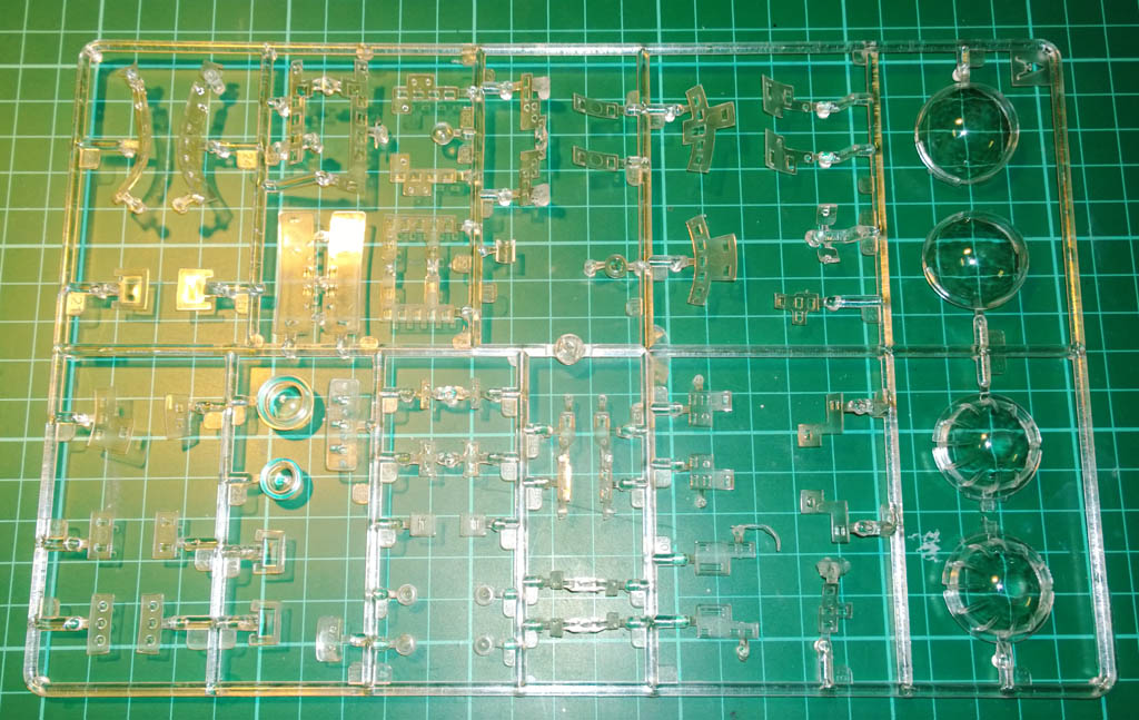
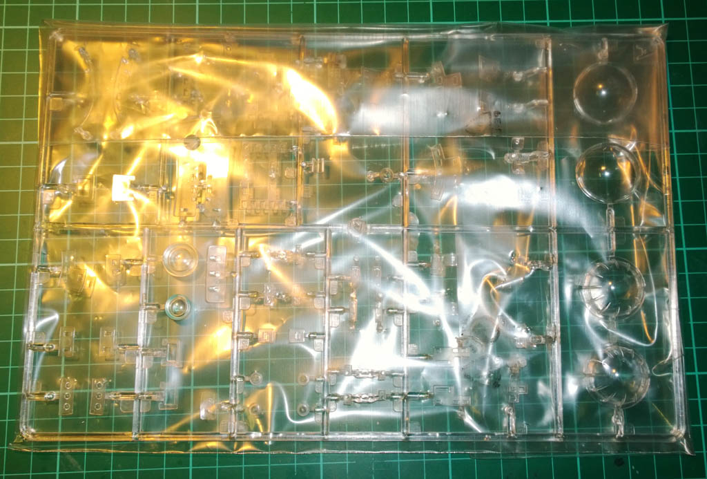
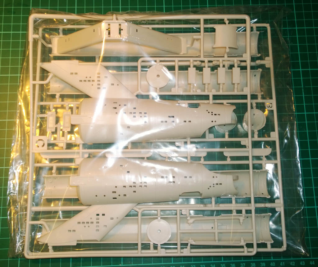
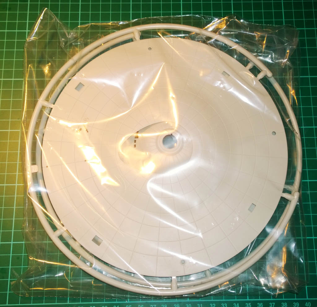
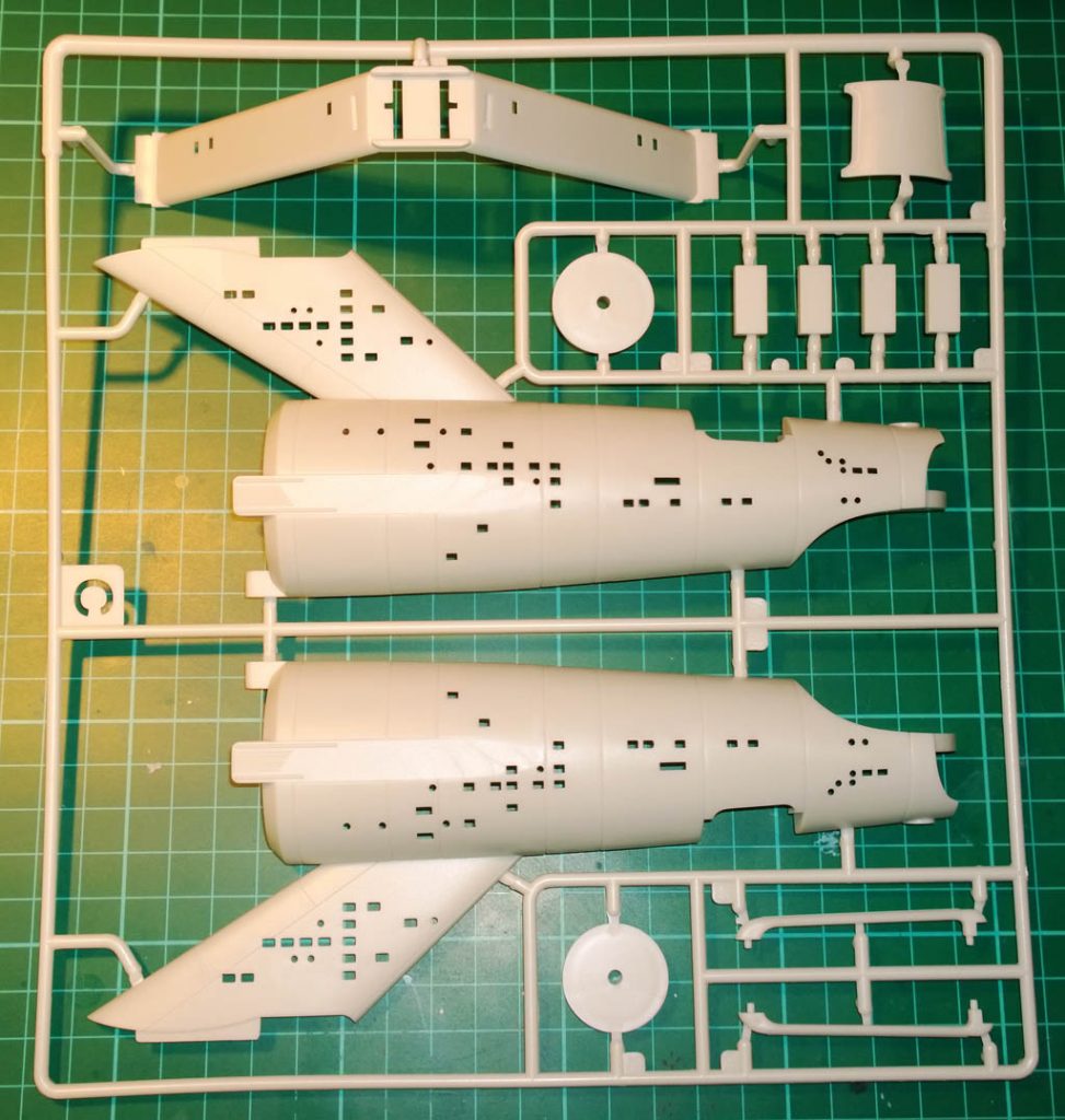
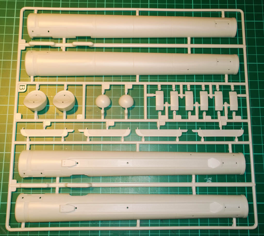
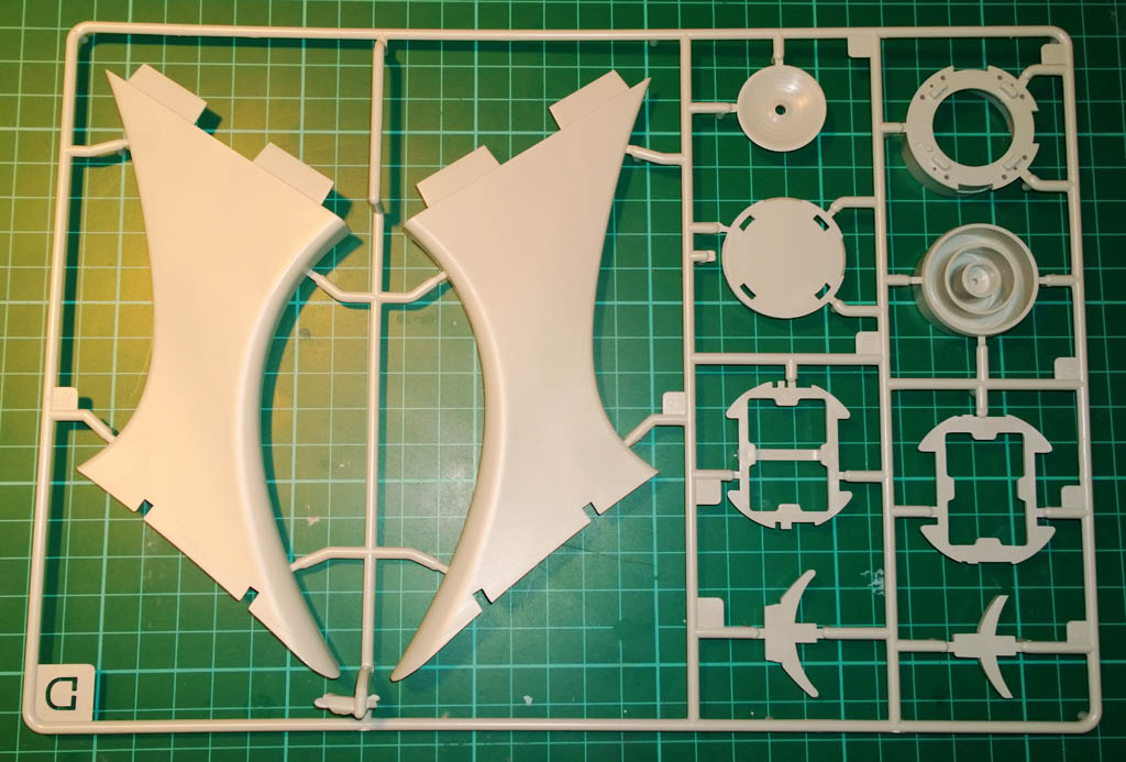
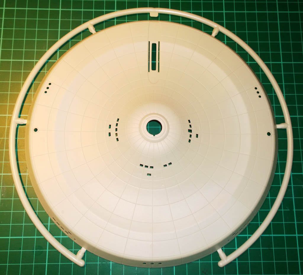
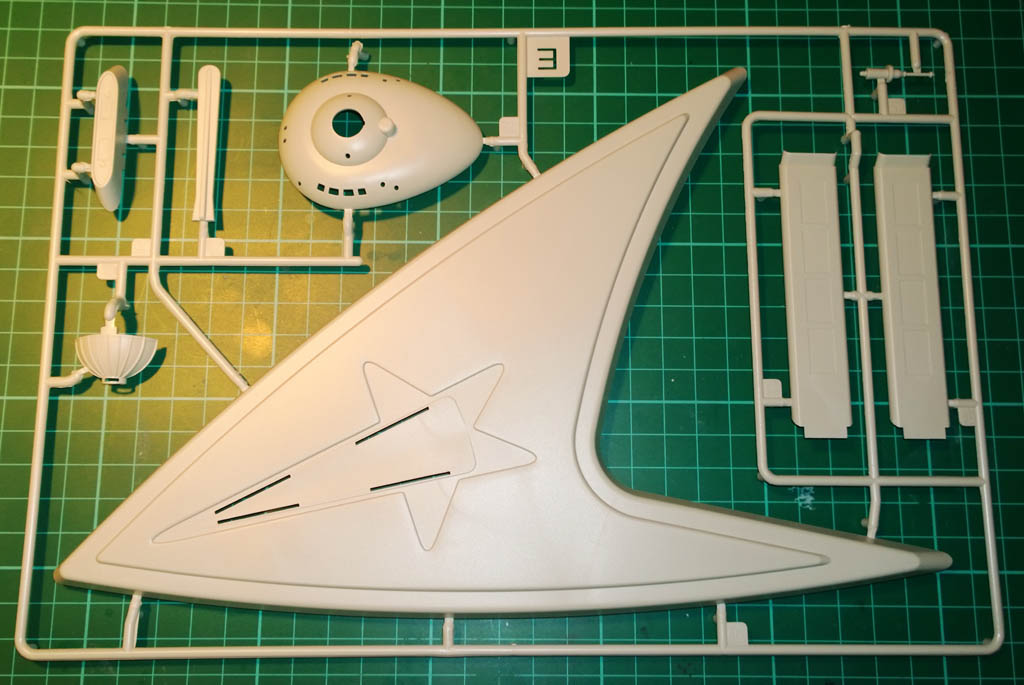
Box and sprue shots:
20th November 2013
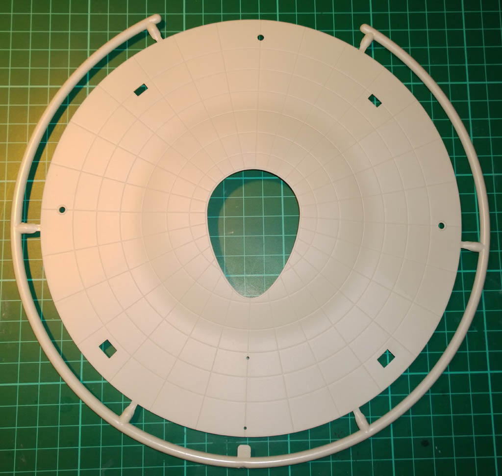
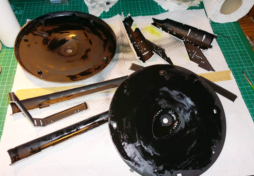
I got the inside of the Enterprise painted with light blocking paint (Humbrol Matt 33 Enamel) this evening… I did the first coat by airbrush and after nearly gassing myself thought it easier and relatively odourless just to brush paint the second coat. Brushing worked better anyway because I could get a thicker coat down and as all the paint will be hidden inside finish is not an issue…
I had to be a bit careful with the brush not to let the paint pool into the corners of the windows, but it went on alright in the end.
Ordered up an Arduino microcontroller board today on eBay, I intend to use that to control the engine lights (and motors if I decide to use them) and also to do the flashing nav lights on the saucer.
26th November 2013
For the last week I\’ve been mainly researching and ordering parts (electronics) and working out how to proceed with the build. At last I feel that I\’ve done enough thinking to overcome my intertia and crack on with it 🙂
My first dilemma was how to handle the windows in the kit. Whether to go with the original clear parts and mask before painting, to paint first then fit clear parts and assemble (and touch up), or to assemble paint and use PVA windows squirted in at the end. I must admit I was tending towards PVA so thought I\’d better test out how it\’d look with lighting.
To test the original clear parts I sanded the back of one of them with 180 grit to diffuse the light through it.
The clear part was dry fitted, and a 3 LED strip of warm white LEDs were blu-tacked in place below the window.
BTW I decided to go over the black light blocking paint with matt white in order to increase the light reflected around inside the ship. It should even out the light a bit.
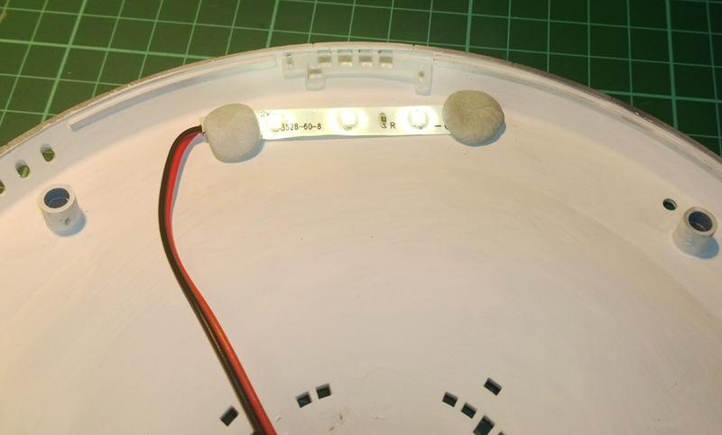
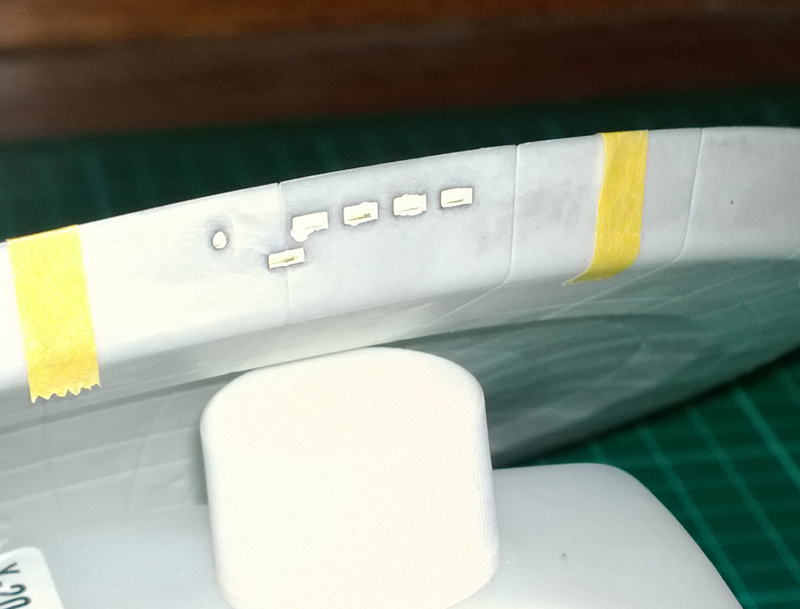
I put the lid on (does the Enterprise have a lid? I bet there\’s a special name for that part), and here\’s how it looks with the standard clear parts…
The lighting is a nice colour and is very even – looks a lot like the original.
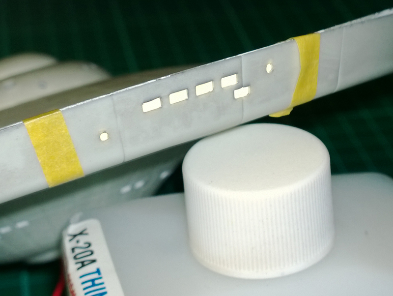
I squirted in some PVA windows and let them dry, then lit them the same way and the results were as below:
Where the PVA windows are very clear and don\’t diffuse the light they give a very uneven light. Also because they dry in a lense shape they tend to distort the light as seen above creating light and dark areas.
Both the above photos were taken with my Lumia 1020 with the flash on, and are pretty representative of how they look in real life. Must say it took a lot of naff photos before I worked on the best way to photograph lights is with the flash on!
So based on the above I definitely prefer the look of the original clear parts with sanded backs to diffuse the light.
And on that basis I’ve decided to paint the ship first, then fit the clear parts and lighting, then button it up and just do local filling/sanding/touching up of the seams.
The first coat of paint has also gone on. For this (after much research) I decided to use Tamiya XF12 J.N Grey with 10% Flat White.
When mixing the paint I just used a pipette to squirt 1ml of white straight into the new XF12 pot – I don’t intend to have any spare paint left over and this way it ensures that the colour will be consistent between sessions.
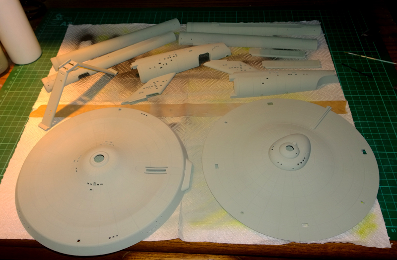
You can’t really see in the photos but the XF12 gives quite a greeny grey under certain lighting conditions but it’s alleged to be very close to the original. Some people hate the colour but I think it looks pretty cool.
I’m still making the transition from enamels and made a right Frank Spencer of the first coat of paint. It went on more like Sandtex than Acrylic but a bit of a light going-over with 600 grit and a re-spray with (what felt like) gallons of thinners sorted it out.
Once she\’s had another coat of XF12 it’ll be time to start installing the lights and sorting out those glowing engines.
For the engines I’m not going to be motorising but will be flashing the engine LEDs with the Arduino controller. Just waiting for a breadboard to arrive before I start coding that.
29th November 2013
I started work on the engine nacelles, these are going to be the most complex part mainly due to the lighting required. On the original model the engine lighting was done with half a dozen flashing Christmas tree lights behind a rotating ‘flower petal’. The lights flashed on and off and the spinning petal gave them a kind of shimmering effect. This created quite a good boiling plasma effect back in the day…
On the bigger kits like the Polar Lights 1/350 scale Enterprise the usual thing is to accurately model the flashing lamps/rotating petal assembly, and I was tempted to go for a similar setup here. I even managed to come across a couple of 12V DC motors in my hoard of crap that were the prefect diameter to fit inside the nacelles. But in the end fitting motorised petals at this scale would have been a mammoth job, and just trying to get a shaft attached to the plastic representation of the petals which come with the kit, and getting that to run true and concentric would have been a lot to ask for. Also since the finished kit will take pride of place in the front room, I didn’t want the noise that the motors would have generated, so I’ve opted to go for a pseudo spinning lamp effect instead…
First job was to give one of the nacelle covers a cateract using some 280 grit wet and dry paper. It was a bit of a choker to scuff up such clear plastic but to make an omelette you\’ve got to break a few eggs…
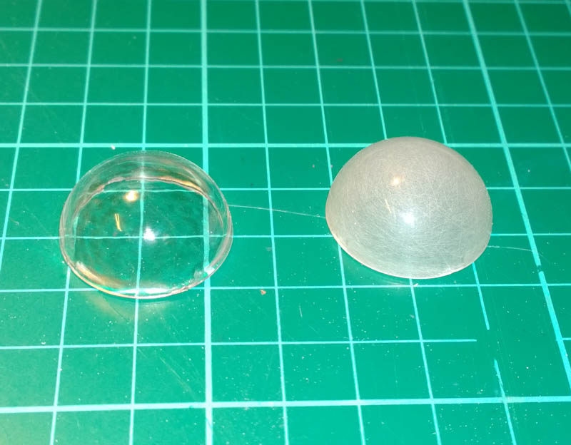
Next up was a coat of Tamiya clear orange, and I no longer felt bad for my earlier sanding antics…
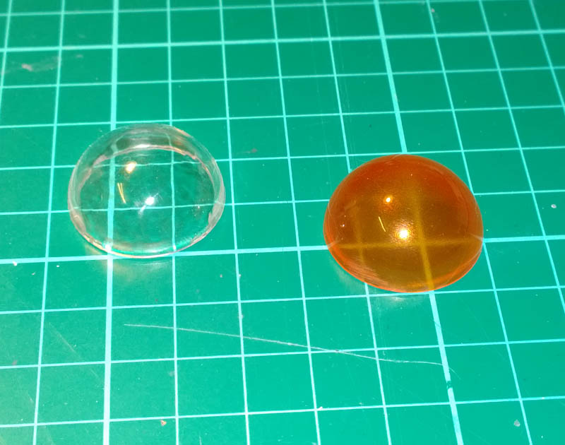
I thought I’d do them one at a time in case I made a Horlicks of one of them and I’d only have to repair one that way.
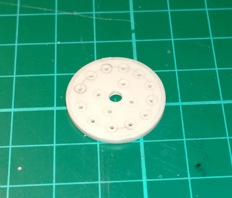
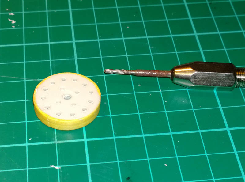
Next I made a start on the blanking disk that fits inside the nacelle behind the lenses. This started off as a plain styrene disk with a spigot on the back. The spigot soon fell to my craft knife and I marked out circles for where the LEDs will go with a pencil.
I ‘eyed’ the markings as it will look better if they are a bit out of true. Well that’s my excuse 😉
The initial pilot holes were easily bored through with a wee drill in a pin vice. (I mean the drill was small, not made of wee).
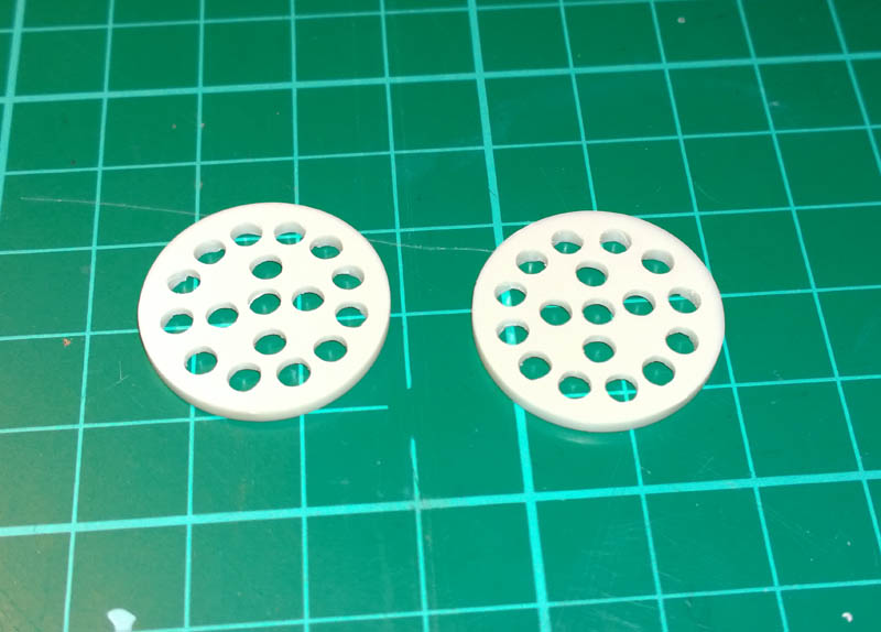
With the first round of holes done, the second disc was de-spigotted and taped to the first one…
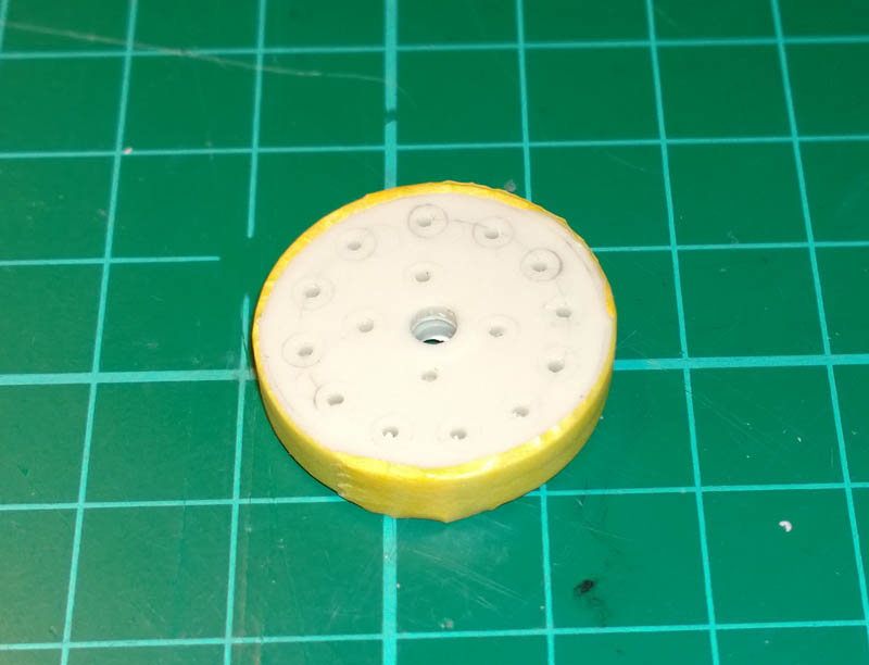
Then the holes were transferred through to the second one with the trusty wee drill.
After that the holes were opened up to 3.2mm (to take 3mm LEDs) using a cordless drill.
And here’s how they look dry fitted in the nacelle behind the (static) petal lense and the orange outer lense.
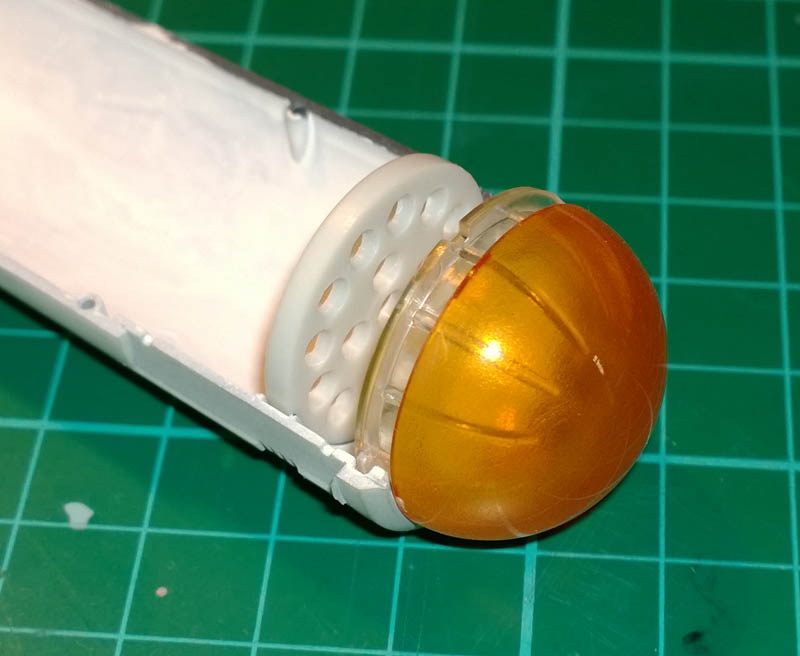
As you can see above it would have been a big job to cut out the inner clear ‘petal’ style lense and getting it running true on a motor shaft – at least without easy access to a lathe.
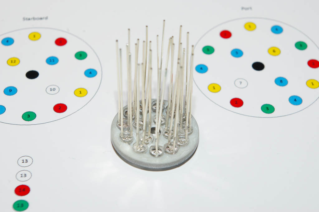
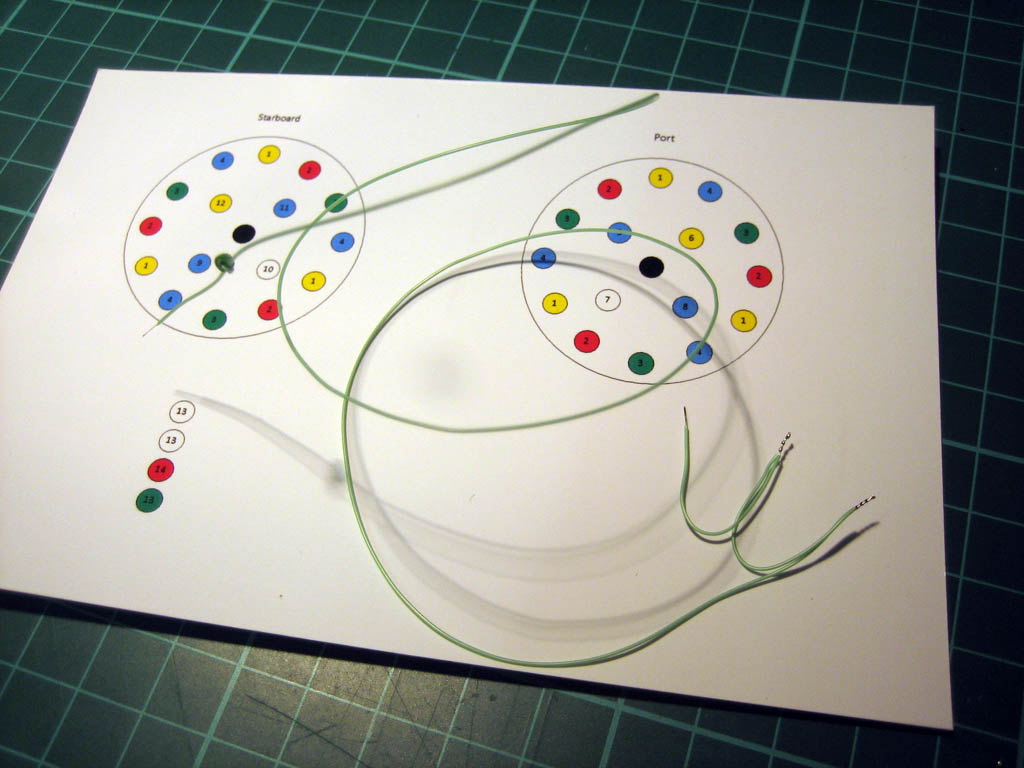
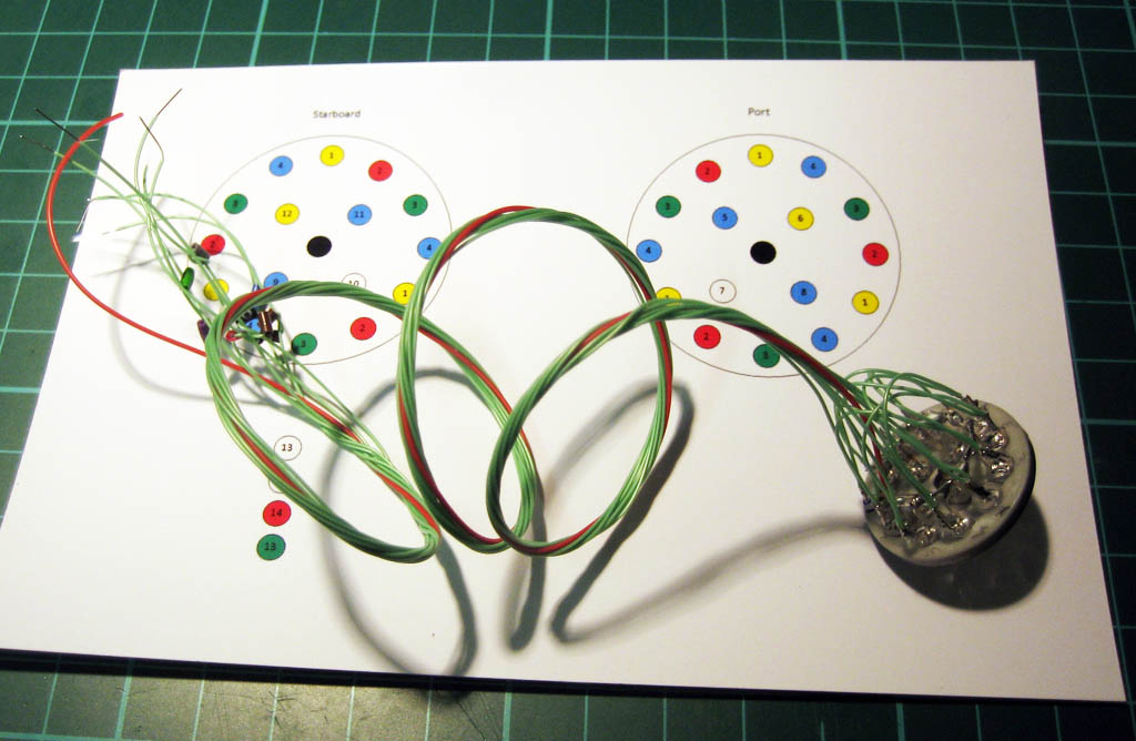
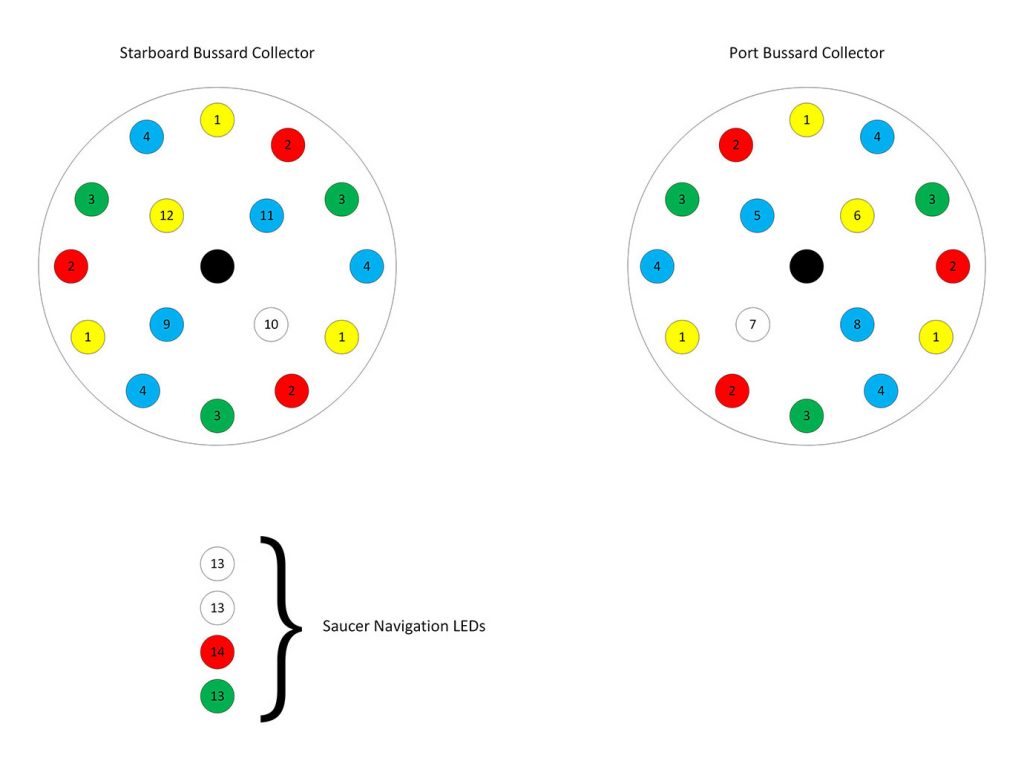
So now we’re starting to get colourful… I sprayed the pepperpot LED holders that I’d drilled with Stainless Steel buffable metaliser (that was the lightest shade I have). And prepared a lighting plan to help me get the LEDs installed in the right holes…
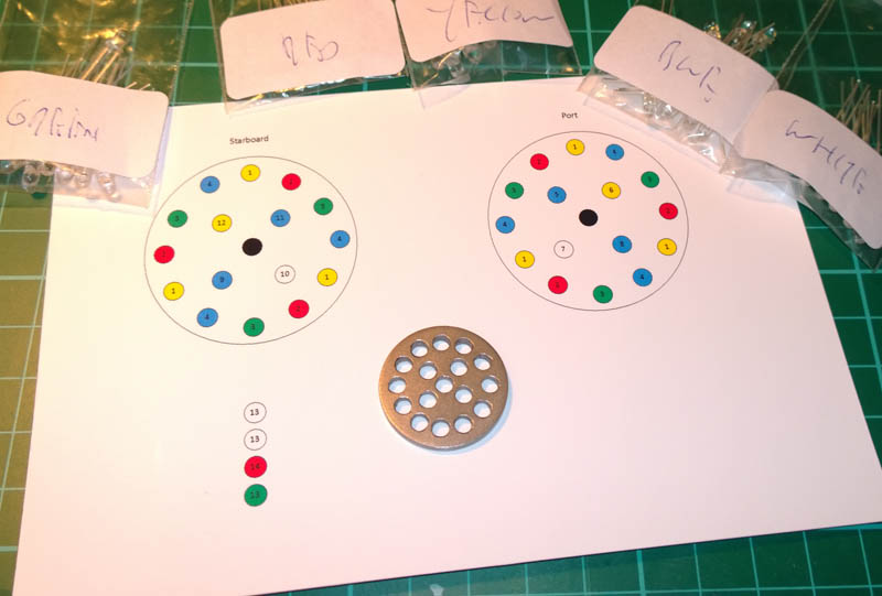
What I’m going for with the nacelle lighting is to have a ring of LEDs (12 off) around the perimeter of the disc, these will chase clockwise on the starboard engine, and anti-clockwise on the port engine. The chaser will be in groups of 4 LEDs, so looking at the above diagram for the starboard engine, the outer yellow LEDs will be all on, then all the reds, then all the greens, then the blues – rinse and repeat…
The chaser LEDs are going to be connected to the PWM channels of the Arduino controller, this will allow me to fade the LEDs out instead of switching them off. So in the above sequence, when yellow is 100% on, the blue behind it will be 75% on, the green behind the blue will be 50% and the red at the end of the chase will be 25%.
The port engine will be a mirror image.
The 4 LEDs in the middle of each engine (2 blue, 1 yellow, 1 white) will randomly blink to emulate the flashing lamps on the original.
I\’m also hoping to add the odd random 10mS full brightness flash to the chaser LEDs to mix it up a bit too.
The 4 vertical LEDs in the diagram are the NAV lights, red & green port and starboard lights on top of the Enterprise lid, and two white below. These will all flash in unison but I’m using 2 digital outs to drive these as the forward voltage of the red LED is different to the green and white and won’t run from the same channel.
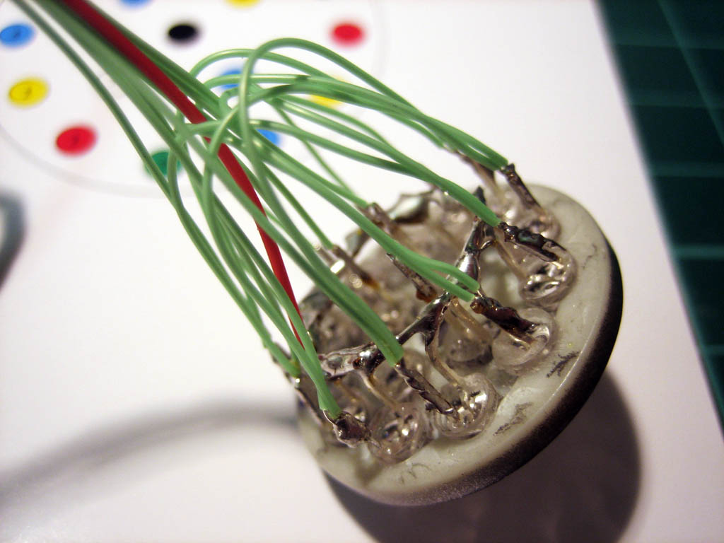
Next up was to populate the LEDs into a pepperpot….
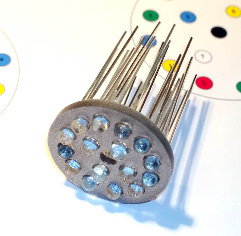
The LEDs are superglued in, and are awaiting wiring.
Gotta say was really ‘fun’ installing the LEDs when they are all clear and there is no way of telling what colour they are other than what bag they came out of… I did flash up each LED before fitting to make sure the colour was right, but still tricky seeing as you have to fit it from the rear which mirror images the diagram you’re working to 😉
So next I will be wiring the LEDs up and will move onto getting the Arduino coded so that it can drive the LEDs – flashing lights should follow shortly…
2nd December 2013
Haven\’t done any more on the engine lights but have managed to get quite a bit of other stuff done…
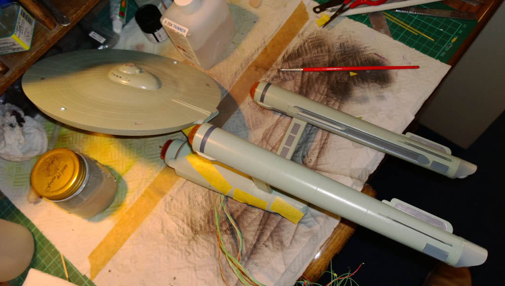
Over the weekend I actually managed to do some glueing and painting! I couldn’t believe it, not sanding, not wiring, not filling and sanding, not researching frikkin paint tones – actual painting and glueing! And here it is.
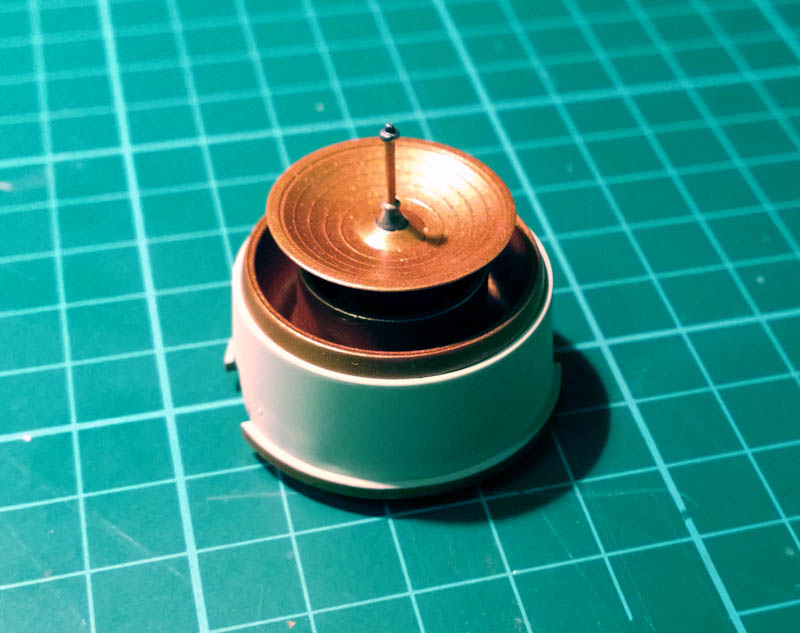
Ok it isn’t much, but enjoyed every last press of the airbrush button, each whiff of thinners and each dab of glue. Ah, I remember when modelling was all glue and paint – none of this attention to detail nonsense – still I digress 😉
Back to the sanding and wiring…
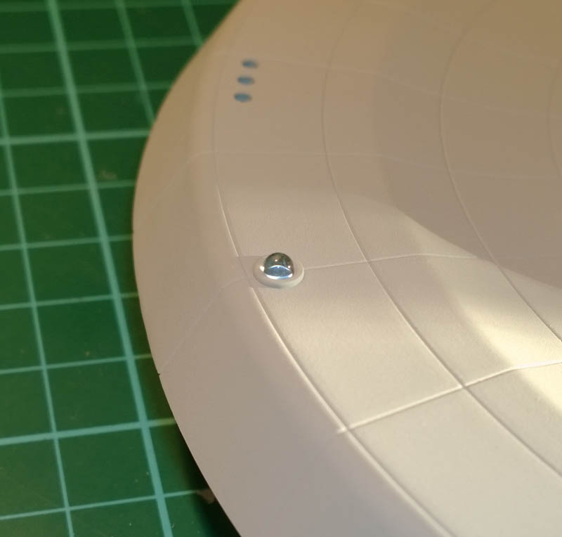
By the way, the sensor above was painted with Tamiya Copper XF-6. It looks much better in real life though, I just couldn’t get my phone camera to get the copper to look right.
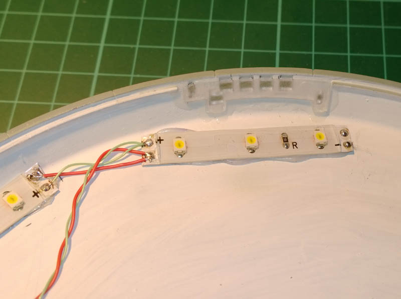
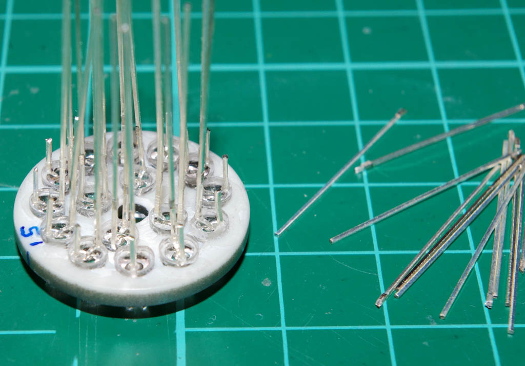
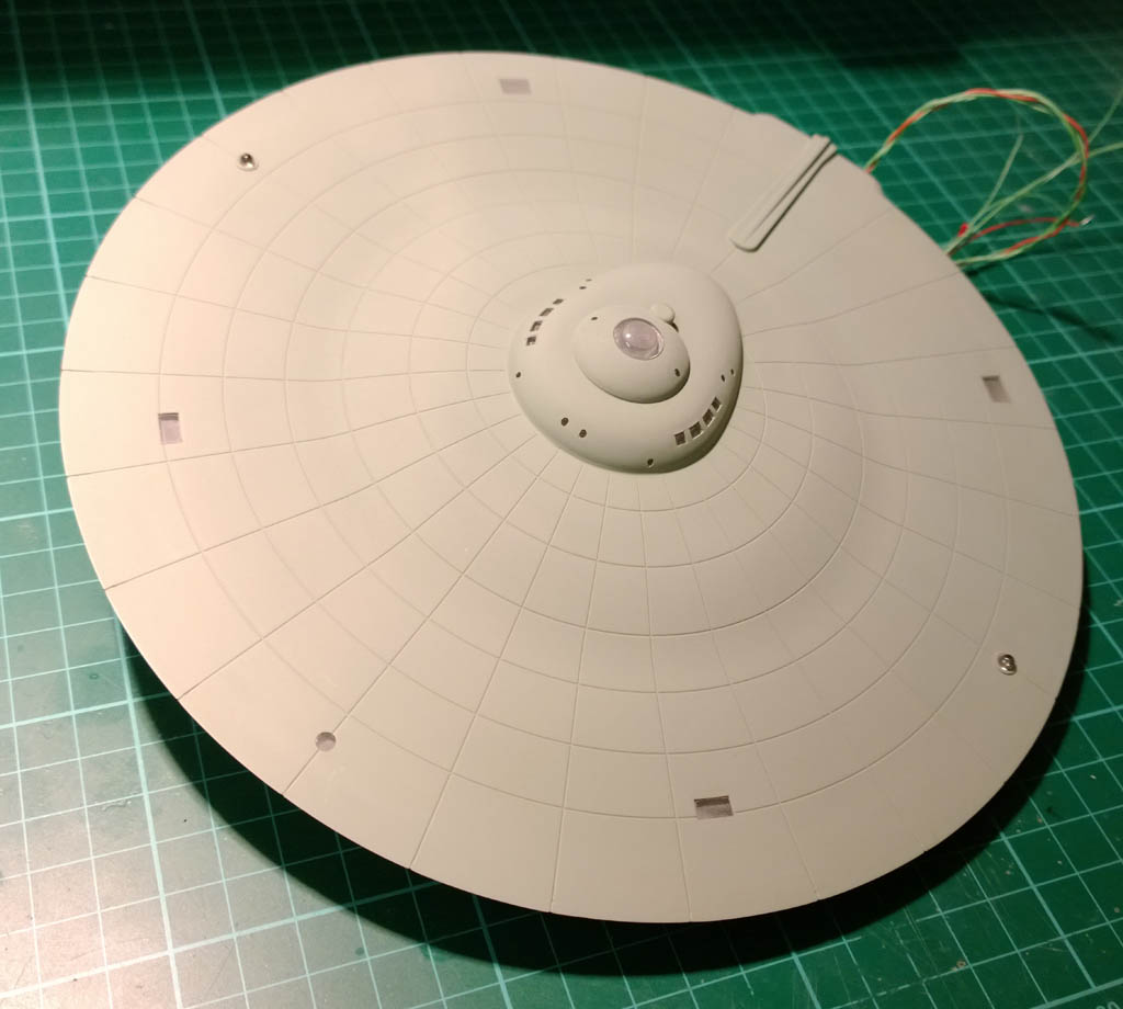
I started lighting the saucer, to do the main lighting of the windows I\’m using a 1m strip of warm white LEDs that I procured on eBay. These run off 12V DC and you can cut them into sections of 3 LEDs as below:
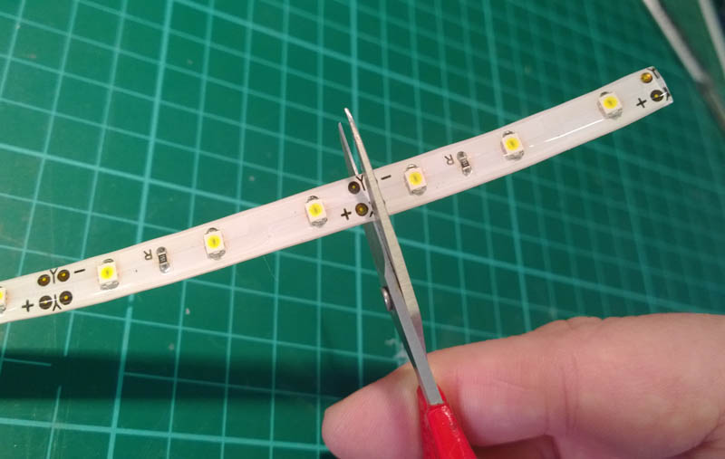
The LED strips (I bought weatherproof ones in error) have a heavy clear coating which needs to be removed before you can solder wires onto the sections. The easiest way I found to do this was to cut through the clear coating with a scalpel and a sawing action being careful not to cut all the way through!
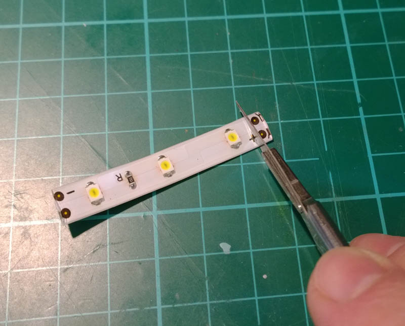
You can then peel off the unwanted coating with a thumb nail to reveal the copper contacts.
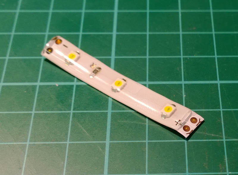
The contacts accept solder nicely and have no problem in wetting, though too much heat can melt the bottom of the strip of LEDs to your cutting mat *ahem*…
For each section of windows, I’m aiming to have a strip of LEDs near by to illuminate the window. Although the strips of LED have self adhesive tape on the back of them, I’m not trusting this and am hot glueing each one in using a hot glue gun:
The saucer also needs 4 round LEDs fitting – these are also held in place with hot glue:
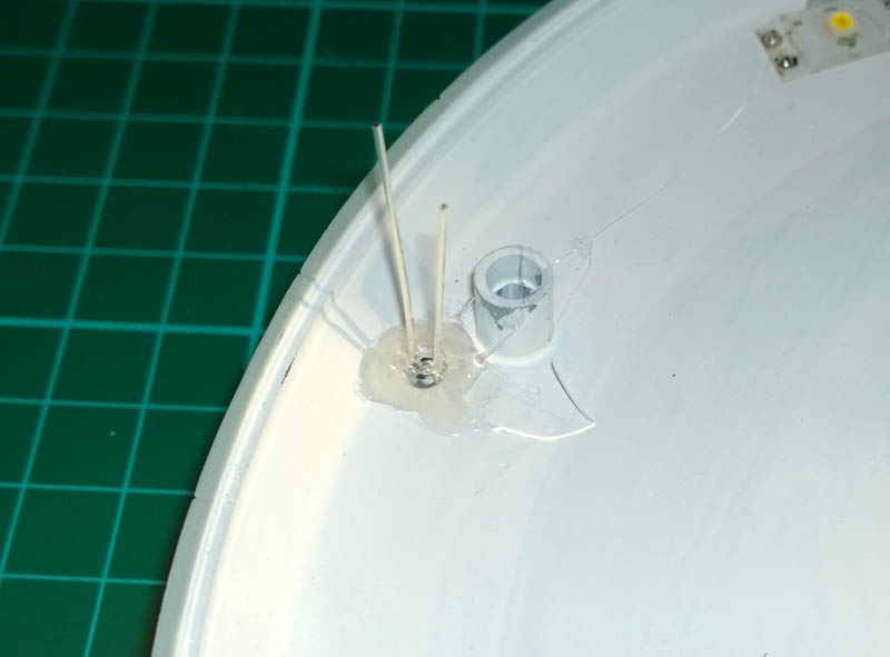
The round LEDs are 3mm diameter and are a perfect fit in the holes provided:
Once the lights has been installed, it was time to fit all the clear parts. This is where the sanding kicked in again 😉 The clear parts are a really tight fit in the holes, especially when the holes have overspray in them, so each window on each clear part had to have its sides sanded or shaved to get it to fit all the way in.
For some of the clear parts it was easier to cut them into sections and fit them bit by bit instead of trying to fit a whole clear panel at once.
Also the clear parts had to have their inside faces opaqued up using 280 grit so as to diffuse the light. This took a lot of time as each and every square pane had a sink mark in it that took quite a lot of sanding to remove.

But once the windows had all been sanded they could be fixed in place with clear PVA. Being careful not to get any PVA on the nicely opaque inside surfaces as we don\’t want to turn them clear again 😉
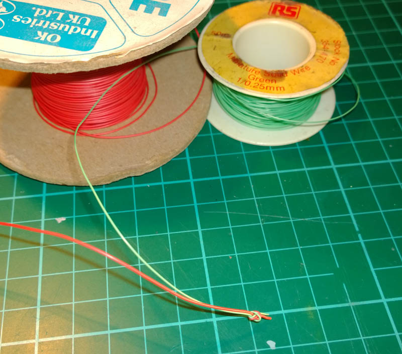
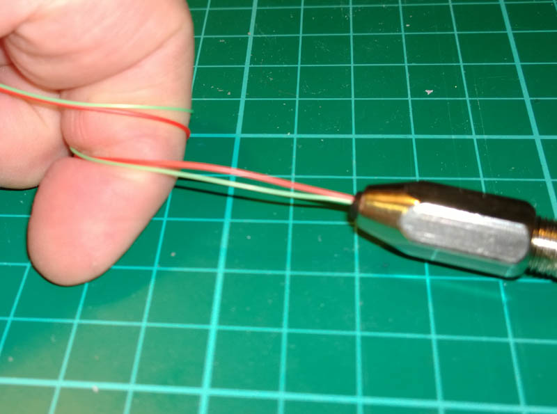
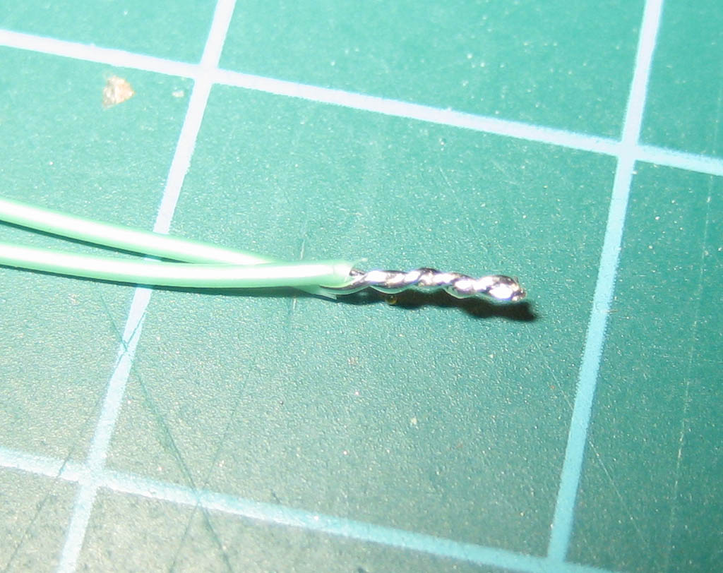
To help keep the wiring (relatively) tidy, where I’ve used a pair of wires I’ve done them as a twisted pair. The easiest way to do this is to tie the ends of both wired together with a good old half-hitch:
Stick the half hitch into the jaws of a pin vice (or cordless drill if you\’re feeling manly)…
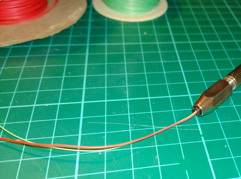
Grab a turn around your finger and twist the pin vice. You can leave as much length of wire between finger and pin vice as you need – 18″ is probably a useful amount to do in one go. If you want to do longer lengths you can use a cordless drill and stick the free end in a bench vice or tied around a nail.
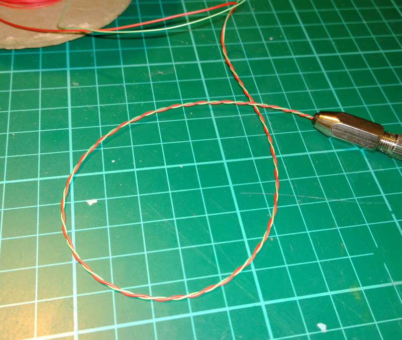
Once it\’s twisted fairly tight, give it a small stretch to set it and there you go…
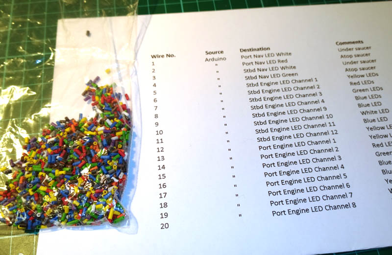
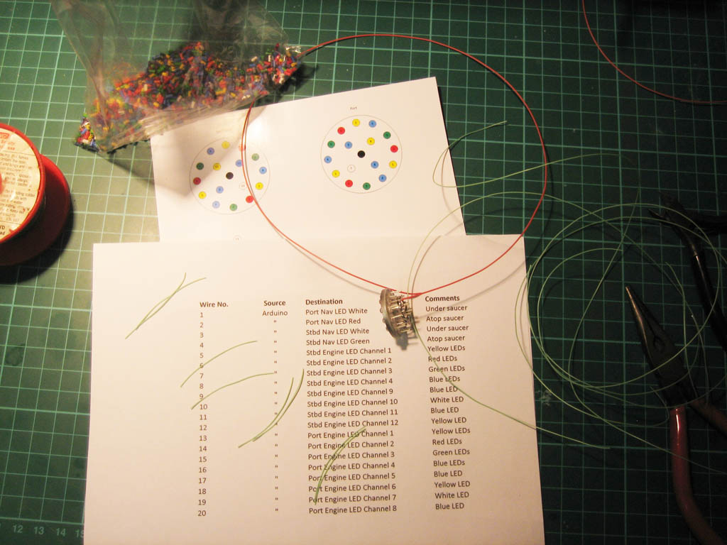
I’m going to end up with quite a few wires coming out of this model all going to various microcontroller I/O channels so I took the liberty of making and printing a basic wiring schedule to help me keep track of what goes where… I also found a handy bag of cable idents in my hoard of useful bits that I know will come in useful one day…
The cable idents are just small lengths of PVC tube, colour coded according to resistor colour codes (Black=0, Brown = 1, Red = 2 etc…) and they also have the number printed on them in case you don’t know your resistor colour codes off by heart. The ones I have are way too big for the wire I’m using so I chose to mark the end of each wire by tying the cable ident in with a half hitch…
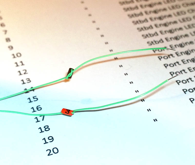
The other end of the wire is soldered to the relevant LED inside the model, and the idented tails will come out of the base of the model when all closed up. The numbered idents will tell me which wire is connected to which destination when doing the final wiring.
You can just as easily use small bits of masking tape and write on the cable numbers, but they can tend to get stuck to each other fall off if you’re not careful.
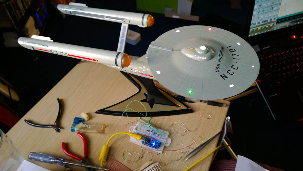
And here we are with the saucer wiring, lighting and glass in place and wired into the micro controller ready to test:
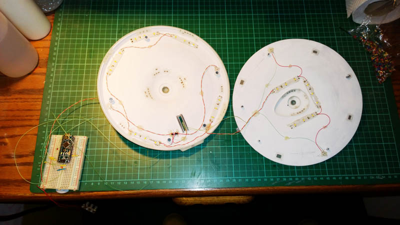
The microcontroller is an Arduino Nano and is an amazing bit of kit. It has 14 digital input/output pins as standard and 6 of these can be driven as analogue outputs (PWM) to allow for fading of LEDs / motor control etc…
Here I’ve got the Arduino plugged into a small breadboard that allows you to easily plug in wires and resistors without having to solder them together. This is ideal for prototyping as you simply push the wires into the holes.
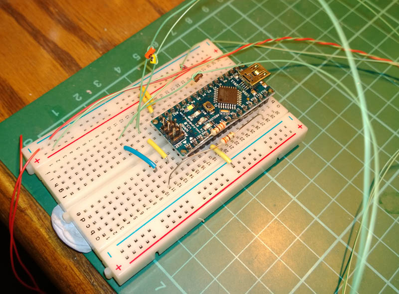
Once the circuit has been finally worked out, the breadboard will be removed, and the microcontroller will be fitted in the base of the model, and the required resistors will be permanently soldered onto Veroboard.
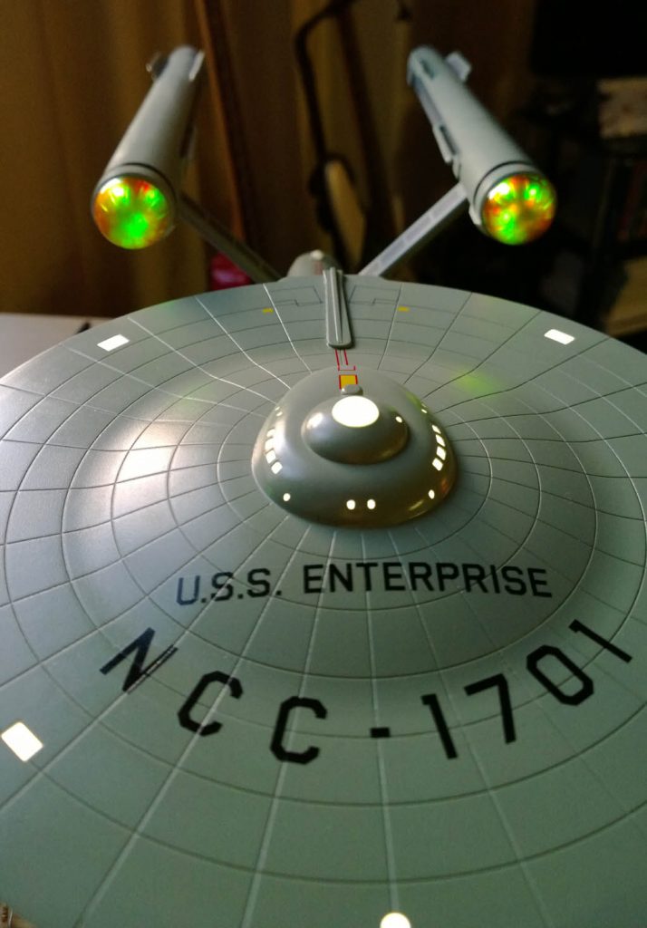
And now the moment of truth, the lid has been dry fitted and everything is powered up and ready to go:
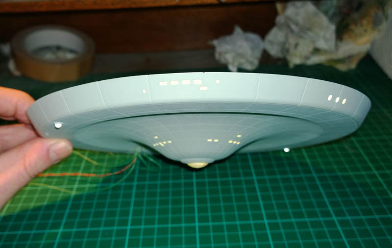
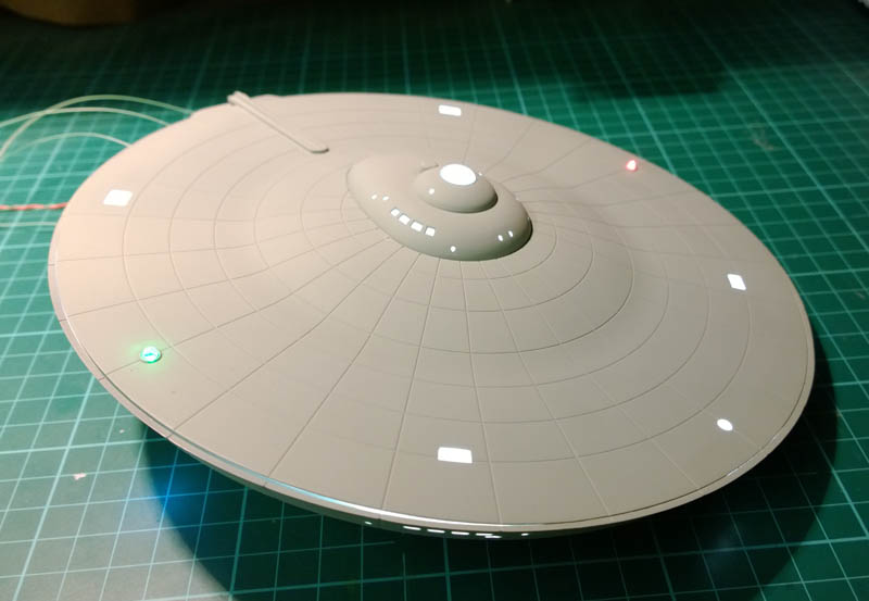
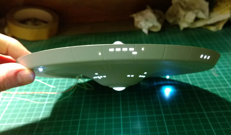
I’m really happy with the way the lighting has turned out so far. I still need to tweak a few windows here and there, some of them need a little dimming down which you can’t see in the photos…
Also the lid will need to be glued down when I’m happy with it all, and then filled and painted. But a small amount of localised touching in will sort that.
The nav lights are flashing courtesy of the microcontroller so until next time I’ll leave you with a short video of the illuminated saucer complete with flashing lights
8th December 2013
Today I wanted to see if I could get the lid (saucer – I mean saucer) closed up. Before I could do this I had a few lighting issues to sort out.
Of the front three windows on the front of the saucer the middle one was a lot brighter than the outside two. This was because the internal post that supports the lid forces the LED strip to be very close to the centre window. As you can see in the photo below I actually had to cut away the bottom of the post to allow the LEDs to slip underneath.
I sorted this one by super-gluing in a bit of 0.4mm thick plasticard as shown circled in red below…
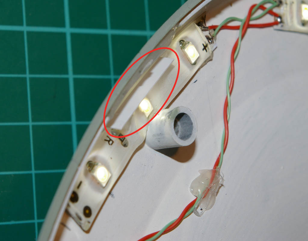
This had the effect of attenuating the light enough so that it evened out across all three windows.
One thing I’ve learned with this build is that the window lighting looks much more convincing if it is done with diffuse reflected light. Any light sources that directly shine through the windows totally blow the scale effect.
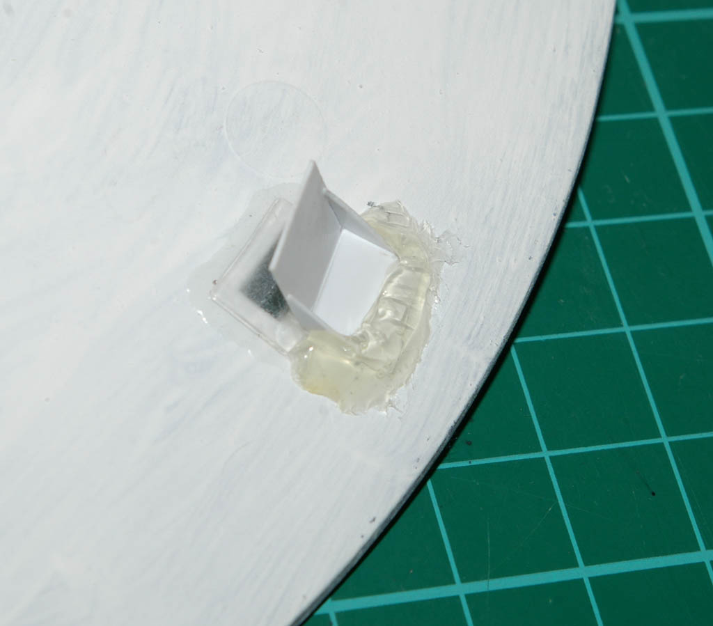
Next thing to sort out was the square windows on the top of the saucer. With these under certain angles you could see right into the ‘core’ of the LEDs which created a really bright spot and again blew the scale effect.
Here’s a shot of one of the windows in question…
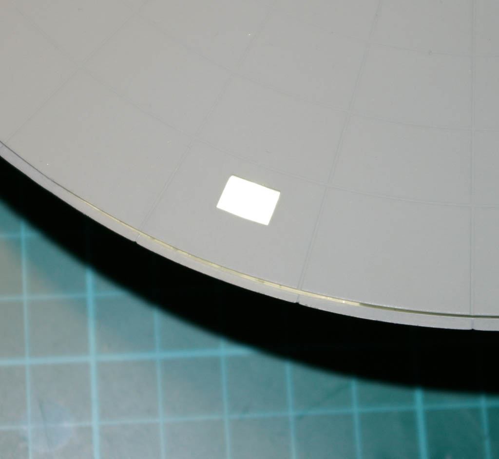
Sorry to say though that no matter what I tried I couldn’t photograph the problem – in the photos the lighting looks perfect whereas in reality you would be seeing a really bright glow in the middle of the window and shade around the edges. Not wanting to turn the afternoon into a photography self-lesson with a really incompetent teacher, I decided to press on and actually fix the issue. (As it happens the above photo makes an excellent “after” shot, so please return to the above shot later for an example of the problem after is has been solved 😉 .
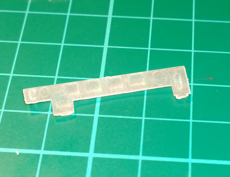
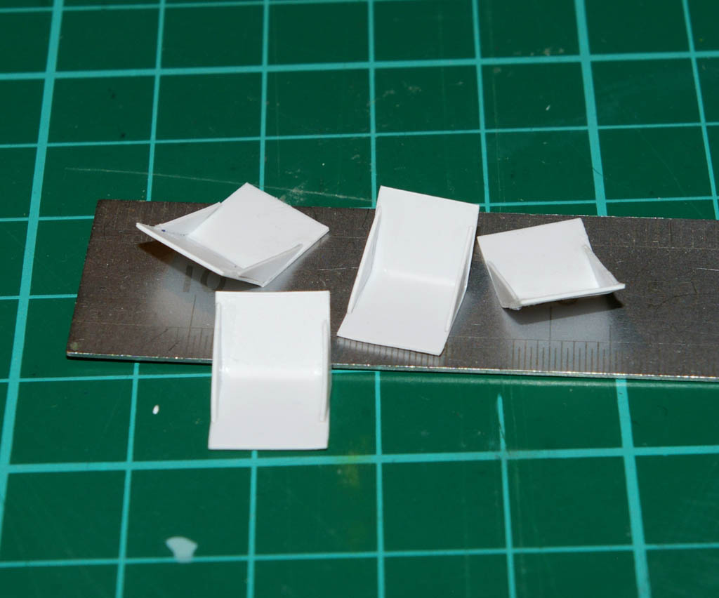
To fix the glare problem I made up a small 0.4mm thick plasticard “sun visor” to glue under the window to shield the view directly into the core of the LED…
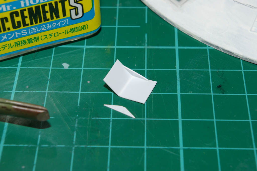
To prevent any risk of the plasticard relaxing back into being straight (and obscuring the window) in the future I made up little webs that were glued into the sides to fix the visors into the desired shape.
Rinse and repeat a number of times…
Initially the visors were held in place with blu-tack while I worked out the best position for them with the lid dry fitted in position and lit, then they were tacked in with Superglue.
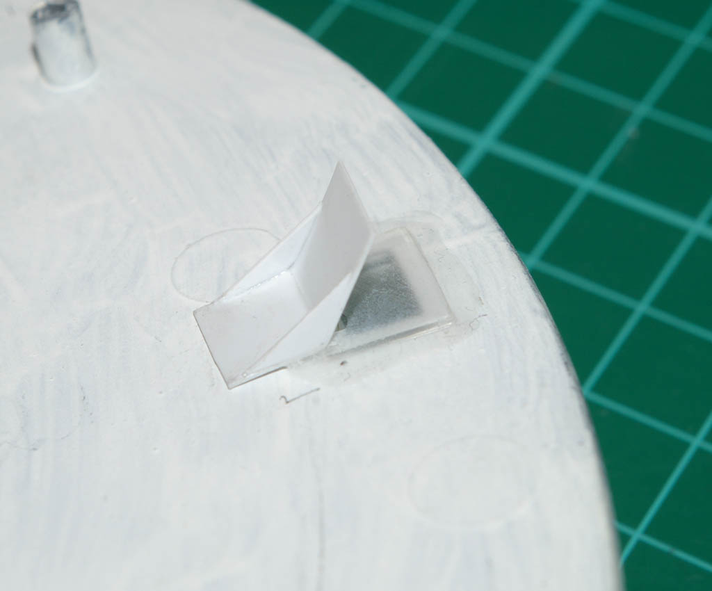
And then a good dose of hot-glue to make sure they stay clinging onto the heavy internal blocking paint.
As you can see above the visors had to be fitted at various angles to achieve the desired effect given the varying positions of the LEDs. Also for one or two I had to make Jumbo visors to eliminate all of the glare.
When the visors were all in place it looked like the window in photo 2 😉 All windows evenly lit and no discernable bright spots anywhere.
With that done, the lid (saucer assembly) was glued up and is now just awaiting filling, sanding and re-touching around the edges.
…So faced with filling and sanding I instantly turned instead to doing more wiring, this time back to the engine nacelles.
9th December 2013
With the saucer lighting completed and closed up I decided to get back to the nacelle engine lighting.
For the nacelle lighting I’m making an array of 16 LEDs which will flash/chase to simulate the motorised lighting assembly in the original model Enterprise.
The inner 4 LEDs will blink randomly. The Outer ring (chasers) will light up in sets of 3 similar colours and will \’rotate\’ around the disk. So for the outer LEDs all the yellows will be lit, then all the reds, then all the greens, then all the blues. Rinse and repeat.
16 LEDs gives us 32 wires to deal with, so the best thing we can do at this stage is tap into all our reserves of abject laziness and see about reducing the wire count (less work to do and fewer wires to route through the ship later).
LEDs have a positive electrode and a negative electrode (Anode and cathode in LED jive speak). The good news is that to save on wiring and time we can just connect all of the cathodes together and run them from a single negative (or ground) wire.
To make this easier for this build I arranged the LEDs so that all of the cathode legs were on the same circle:
Here’s a Photo-shopped picture to (hopefully) illustrate the idea:
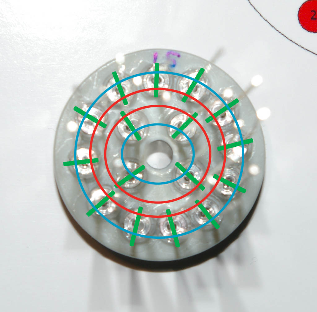
In the above rear view of the LED array, the legs on the LEDs are all aligned to point to the centre of the circle… I’ve drawn green lines that shows the alignment of the LED legs.
The anodes (positive electrodes) all lie on the blue circles, the cathodes (negative electrodes) all lie on the red circles.
Sorry for the clarity of the photo BTW – I’ve had a bit of a mare with photography this evening. First my usual phone camera packed up, so I fired up the DSLR which ran out of batteries and I ended up using the faithful (but senile) Ixus 50. The above photo was taken with the DSLR but trying to get clear photos of things that are silver, shiny, see-through and small seems to be beyond me lol 😉
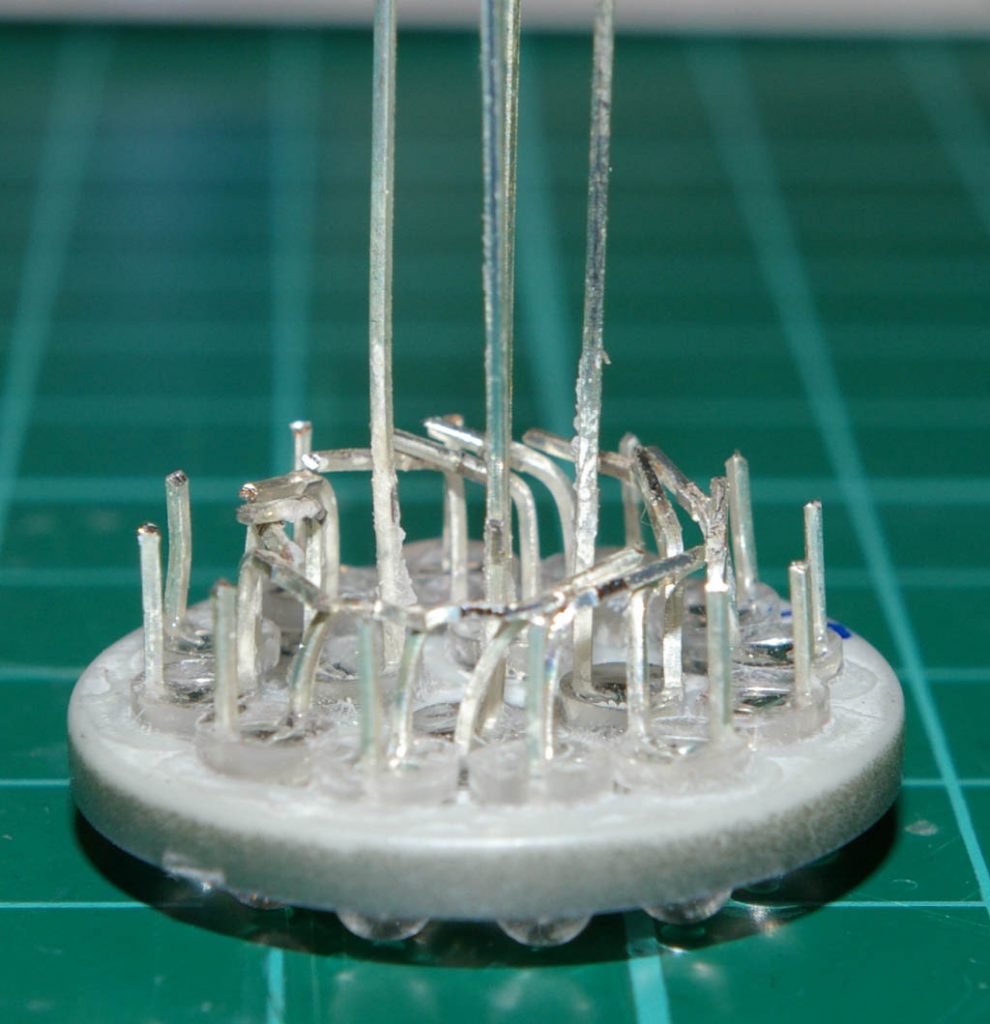
Anyway, given that the legs of the LEDs are arranged in a cunning pattern, the first job to do in wiring them up was to nip off all the anode legs of the outer ring leaving about 5mm protruding…
With that done, the ring of cathode legs were bent 90 degrees to the right at about the same height that the anodes were trimmed off at…
Again, sorry if the photos aren’t that clear, damned shiny-see-through-chrominess :-$
And here’s another shot this time from the side that hopefully shows it more clearly… (The middle LED anode legs are still intact at this stage)
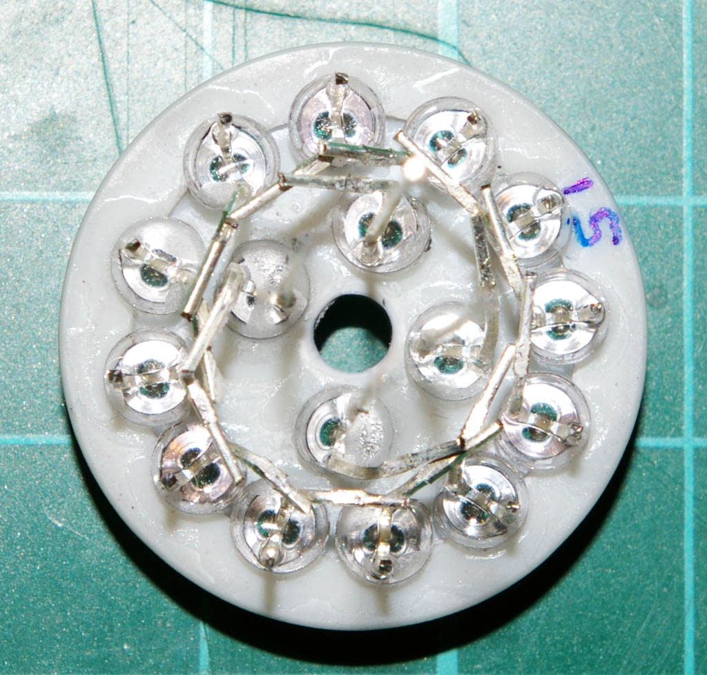
With all of the cathodes pretty much touching each other in a ring around the disk, they could be liberally soldered together… (Or conservatively or using labour depending on how you vote).
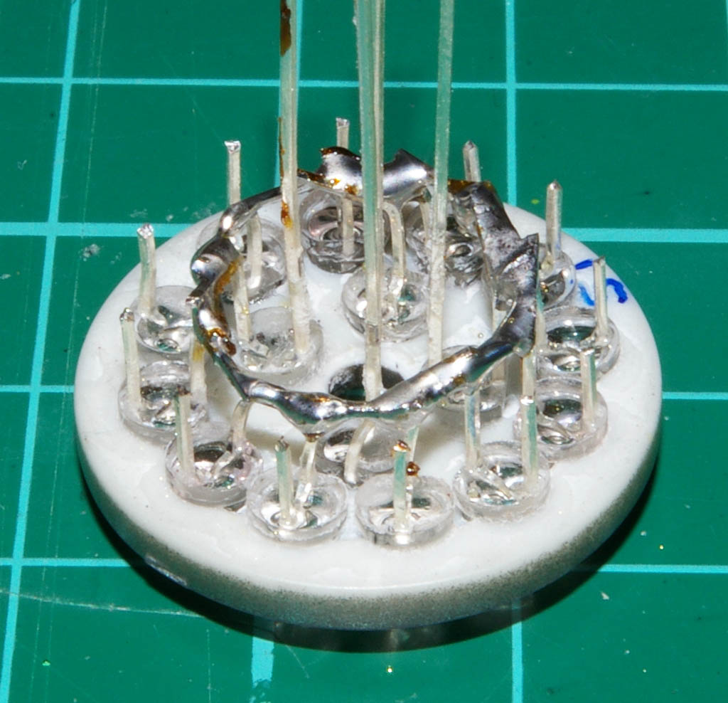
So in the above photo, everything in the solder ring is a cathode (negative leg) and everything else is an anode…
However, the wiring economy was not over by this point, we\’d eliminated 15 wires by ‘commoning’ the grounds together, but I also wanted to reduce the number of positive wires (anodes) going to the microcontroller. For this each similar group of colours in the outer ring of LEDs are also commoned together. So all the outer yellows are connected to the same wire, all the same outer reds, all the same outer greens etc… This means that instead of 3 yellow chaser LEDs requiring 3 wires, they can all be driven from a single wire that connect to all three inside the nacelle.
Note that for this build I’m placing the required LED current limiting LEDs inside the base of the model and not close to the LEDs. Usually you’d wire this with one current limiting resistor per LED and mount them on the LED but for wiring and microcontroller channel economy I’m doing things a bit differently here…
Time to prepare the wiring. For any job like this it’s best to cut all the wiring lengths together in advance. That way you get a neater end result than just cutting wires as you go.
It’s also time for the wiring schedule to come out again to make sure I’m numbering the wires correctly so they can be hooked up properly later.
Confession/disclaimer/crap attempt at hypnosis: In the above photo you can see a single red wire connected to the LED array. Now I’d like to ask you to pretend that this is a black wire and not a red wire (look into my eyes, not around the eyes but into them…). The red wire above is actually my ground wire which by tradition (and good practice) should be black, however all I had in my stash was red and green and the red is slightly heavier gauge than the green – hence I decided to use the electrically better (thicker) wire for ground and not one of the correct colour. I’ve caused myself all kinds of pain when I have to connect a red wire to a negative terminal (mental pain not electric shock) but I’d highly recommend when you wire things to choose the traditional colours instead of my half baked scheme 😉
3,2,1 – you’re back in the room…
For this wiring scheme I’m going to need to daisy-chain from one LED to another. For this it is always best to use a ‘mechanical joint’ for the wiring by twisting it together before you tin it and solder it. This is where we want to have two wires soldered onto one pin, and the use of a mechanical joint allows you to solder the wires onto a single pin without them pinging apart and flicking solder in you eye.
Note: If you want to go totally “Isombard Kingdom Brunel” over the wiring job, you’d actually wrap the first wire around the second, and then wrap the second wire around its destination pin. Kind of a mechanical joint which then forms a mechanical joint.
Here’s one of the LED chaser wires soldered up and ready for attachment to the LED array…
The single end on the left will go to the microcontroller (via a resistor) the three daisy chained ends on the right will each go to an LED (yellow in this case).
Once all the wires were prepped as above, they were soldered onto the anode pins of the LEDs.
And here’s the finished engine nacelle lighting loom looking in all it’s glory like the optic nerve of a Terminator…
So there we go, 32 LED pins handled with just 9 wires running to the microcontroller.
Next job will be hooking this up to the microcontroller and writing some code to chase and flash the LEDs – gotta say it’s going to get pretty freakin Christmassy looking on my workbench
16th December 2013
Here’s another update on my 5 year mission to boldly buy cleaning products where no self respecting man has gone before…
I’ve got quite a lot done since the last update, have put in a lot of hours trying to get her finished for the Christmas day deadline. Unfortunately not too much to show for my efforts as it’s mainly been glazing, sanding, filling, much painting of flat greyness and a load of microcontroller programming…
Here’s a few pics of the state of play at the moment…
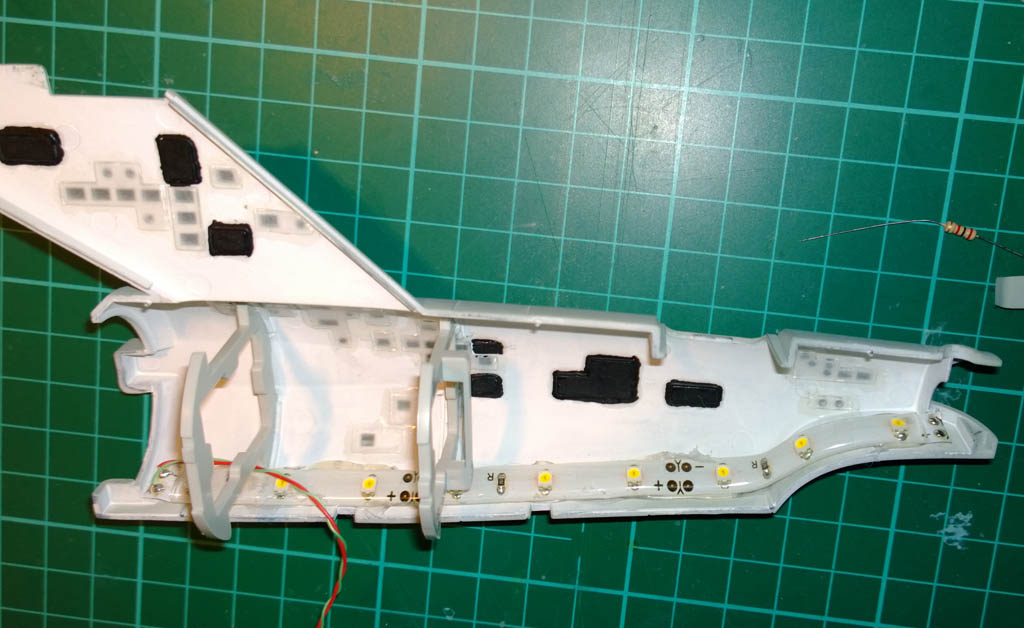
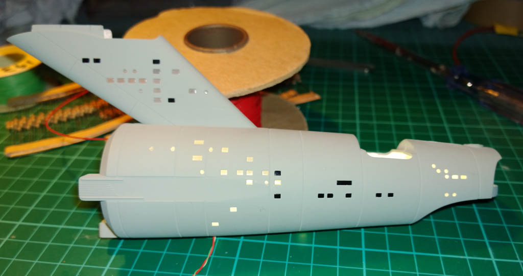
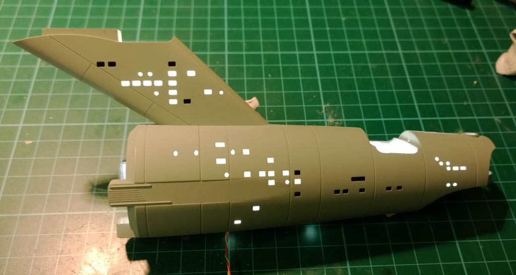
I started working on the secondary hull, which mainly consisted of fitting the glass (this kit is like a self build greenhouse in places). The Revel instructions call for the clear glass to be back painted in white and for the darkened windows to be painted in black:
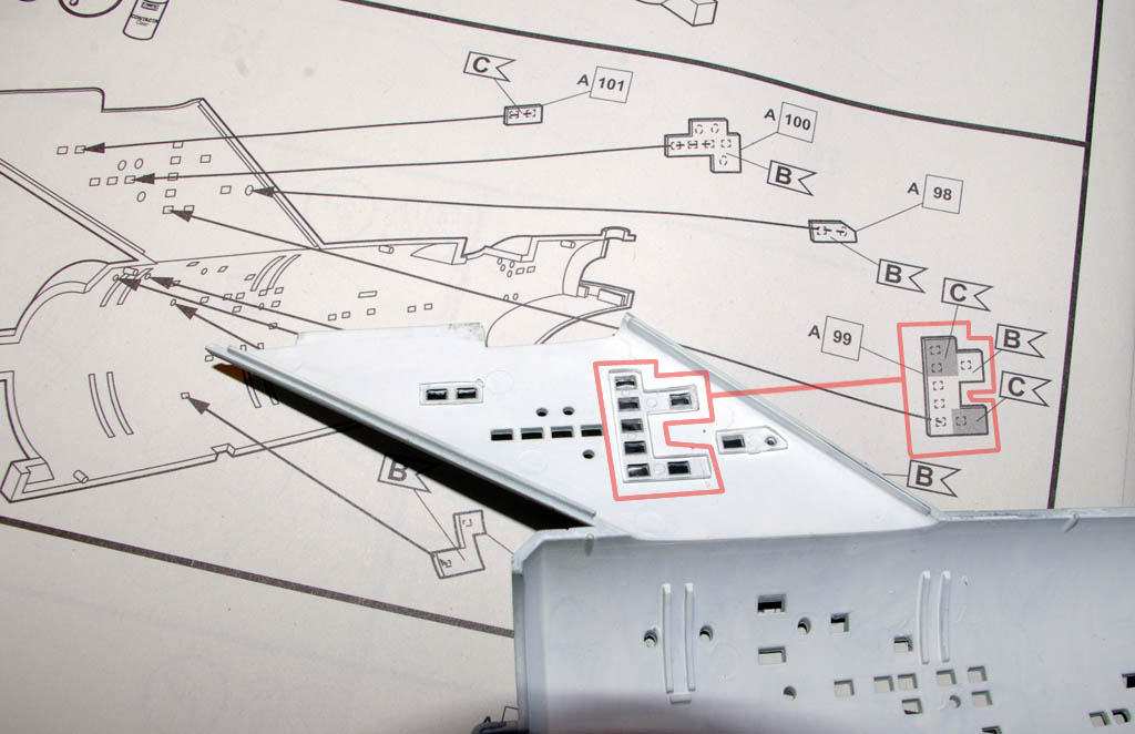
Seeing as I’m lighting this kit I won\’t be painting the white windows (Colour B in the instructions), and I felt sure that if I just back painted the darkened windows in black (Colour C) then the light would refract inside the glass and illuminate the windows that are supposed to be black.
So I decided to cut the window parts up and isolate the darkened windows so that they can be painted black around all their edges, totally light blocking them.
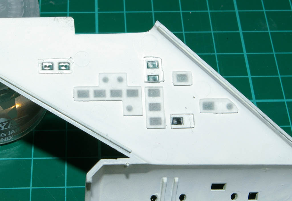
I made sure the blackened out windows are well isolated from the others by trimming off the connecting glass between them.
In the above pic the illuminated windows have been sanded on their backs to cause them to give a diffuse light, the one that are to be blackened have been left clear as sanding will have no effect once they are back painted with black.
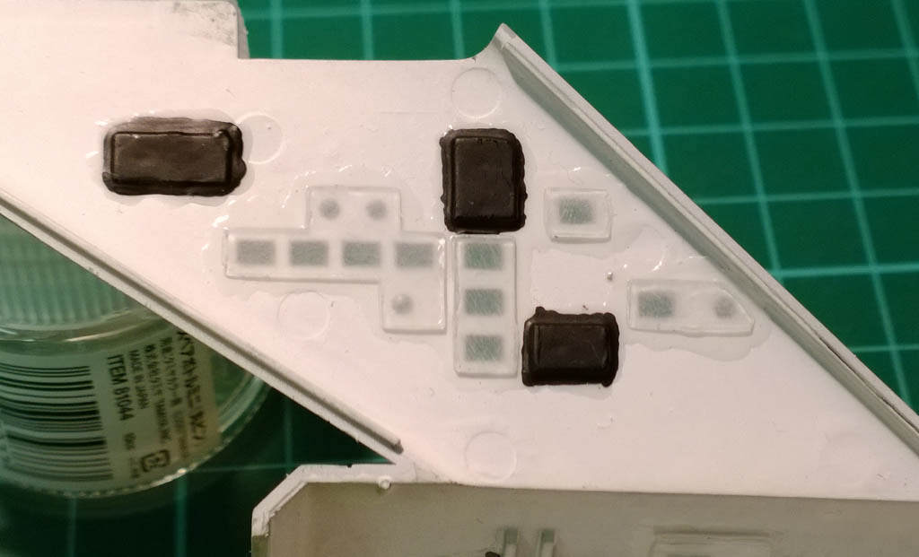
Here\’s the isolated and light blocked glass after PVA’ing in place and having 3 heavily brushed coats of Tamiya Flat Black.
Rinse and repeat for the rest of the secondary hull parts…
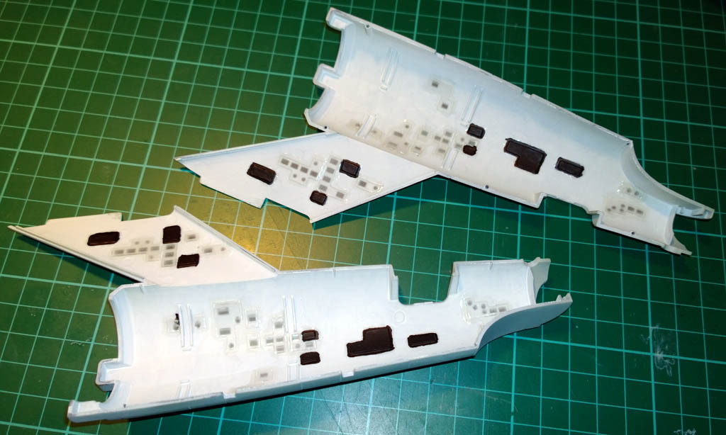
Again this was quite time consuming as pretty much every glass part had to have the sides of the window panes sanded to fit, and also the backs had to be sanded to make them opaque, removing any sink marks (one per pane) 😉
I managed to get the first engine nacelle lights wired up to the microcontroller last week, and gave them a test spin. They looked just right but I was unable to get a video of them in action as my phone decided to pack up and I had nothing to video them with… So I’ll have to see if I can get a video up of the spinning lights in action once I get the nacelles onto the secondary hull.
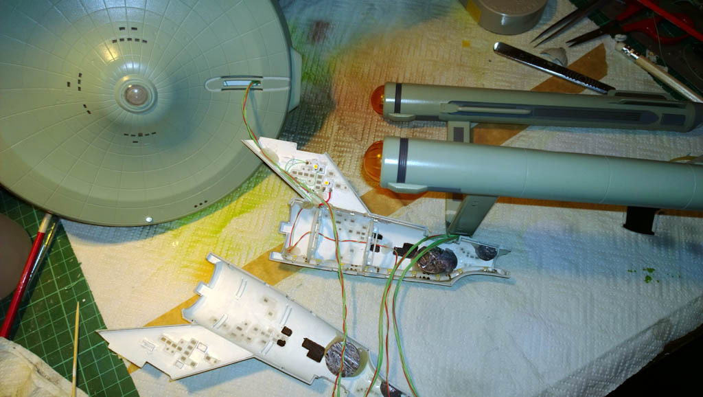
Still, I did get the second engine nacelle LED array built and tested, and both LED arrays have been installed into the nacelles.
As you can see above, they’re currently masked and being painted, so shouldn’t be long before they’re in place on the secondary hull.
The saucer is now complete – all filled and painted. Gotta say Humbrol Maskol saved my life with masking some of the windows that got a bit close to the touch up area.
So next up will be finishing off a bit of painting and hopefully not far from attaching the saucer and engines to the secondary hull (complete with lighting) and then it can be powered up in its final form…
As I mentioned, I did a load of coding last week to get the flashing lights all working simultaneously. I’ll post the source code here once I’ve got a video up of it in action (the code will be more relevant then). I’ll go into more depth on the programming side of the Arduino in a future post.
21st December 2013
This week so far has been mainly working on the paint and secondary hull wiring so I can get her to the point of assembly prior to the final lighting tweaks.
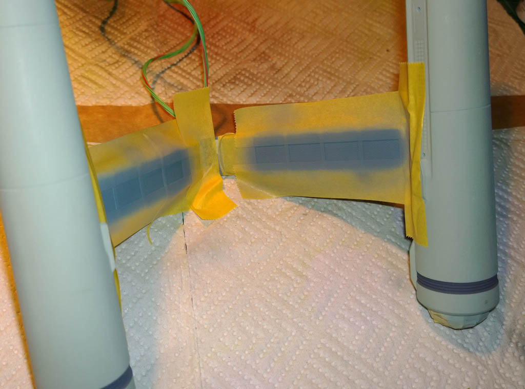
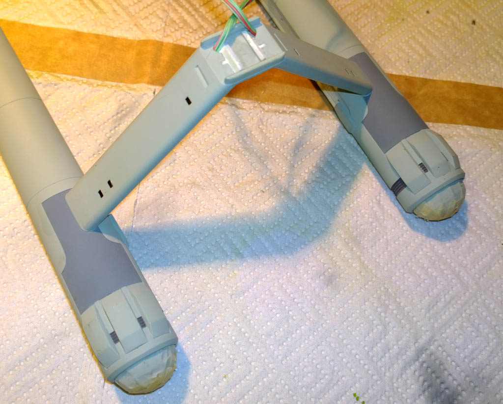
The engine nacelle pylons masked and painted with Tamiya light grey XF-66.
After this I gave them a dry brushing with Tamiya copper to give them a bit of depth.
And under the nacelles touched in again with light grey.
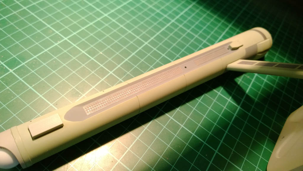
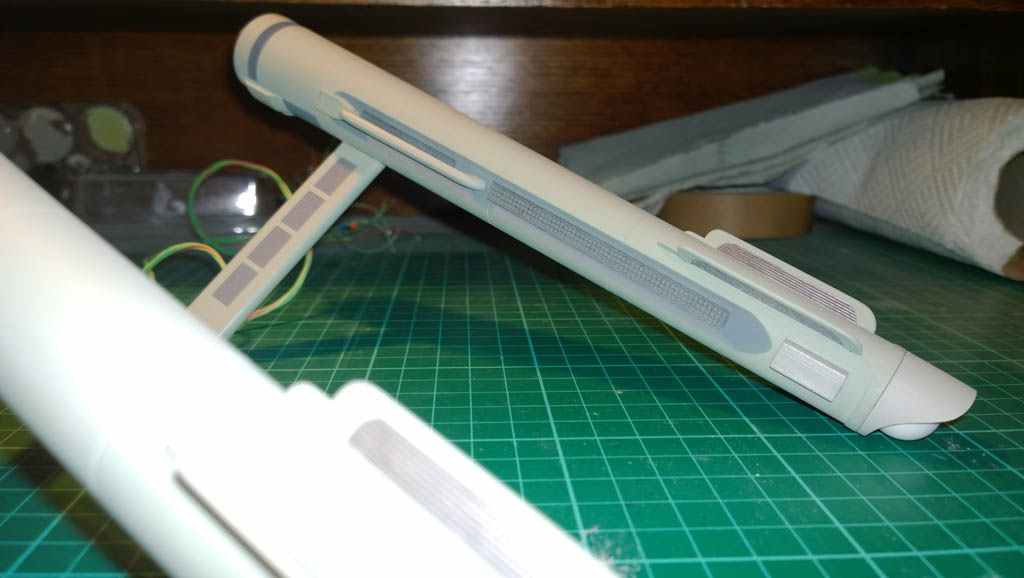
Here\’s the sides of the nacelles masked up and sprayed with the ubiquitous XF-66 light grey…
And again after unmasking:
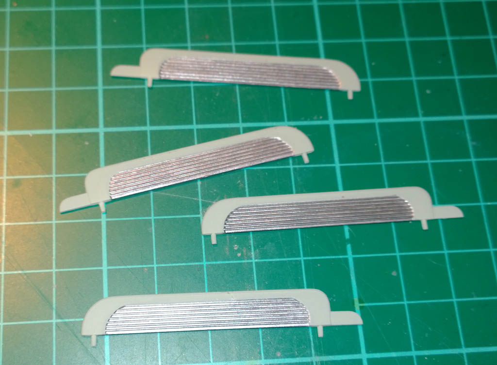
Once dry I re-masked the moulded grills within the grey area…
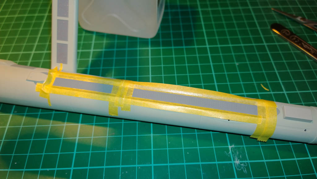
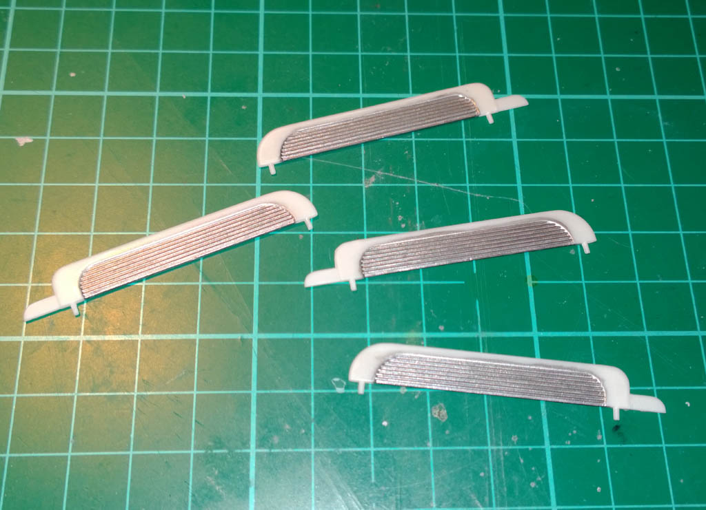
And then dry brushed it with Mr Metal buffable stainless steel…
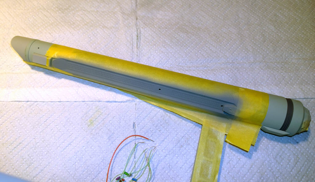
For the intercooler loops I hand brushed these with Mr metal buffable stainless steel…
And then masked them with a combination of Tamiya tape and Maskol (I found it really easy to hand paint a big blob of maskol to fit the curved area required rather than hand cut 16 curves from tape).
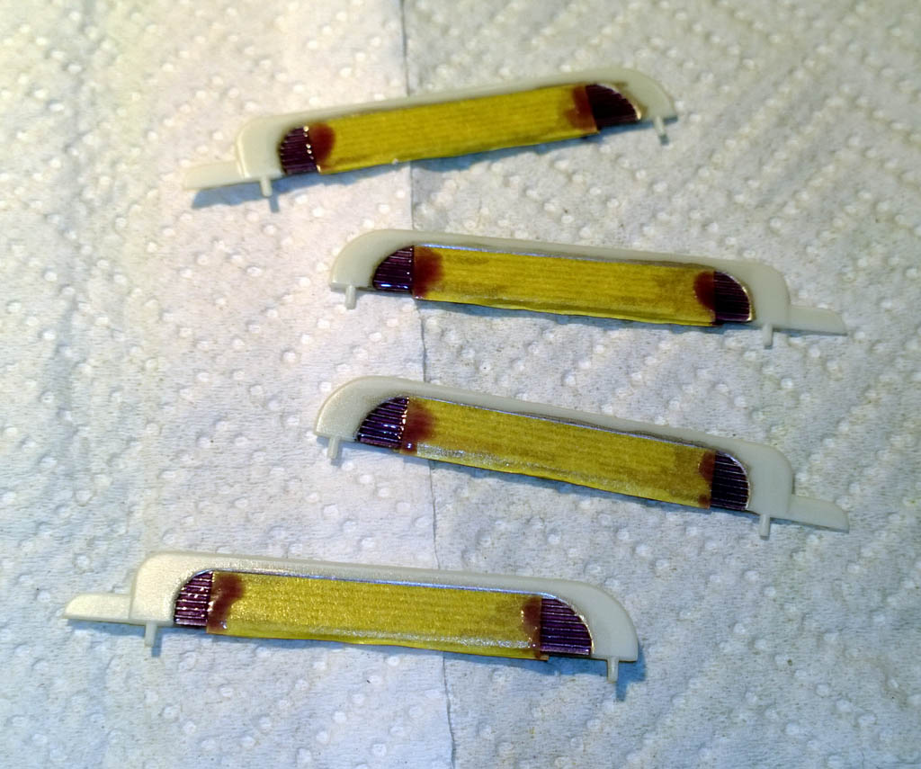
A quick spray of XF-12 and an unmasking (being careful not to rip the Maskol off) and the intercooler loops are ready to go…
And here we are with the engine nacelle assembly painted and ready for Klear…
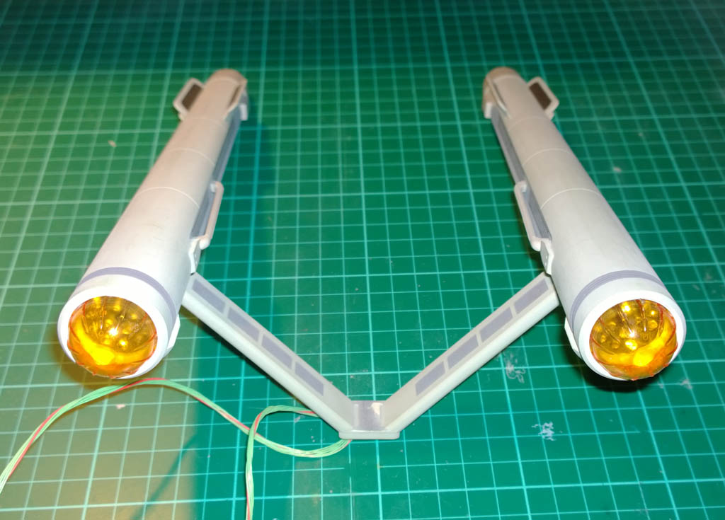
In the above photo you can see that I\’ve painted the clear end caps (Bussard Collectors I believe they are also known as) with clear orange. There is still a set of outer clear end caps to fit which are also painted in orange but I’m going to fit these a bit later. You can just about make out the LED arrays that I fabricated earlier behind the orange lenses…
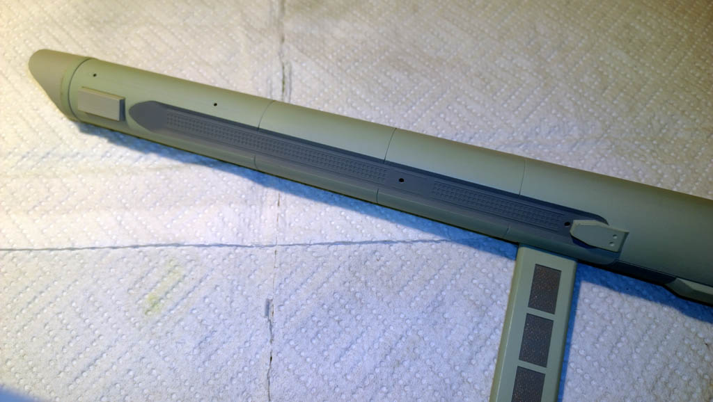
Another view of the (nearly) finished engine assembly…
I actually had a change of mind on the colour of the nacelle end caps (far right of photo). I originally painted these with Tamiya Royal Light Gray (XF-80) but found that they looked too light and almost like unpainted plastic. So after this photo was taken I went back over them with light gray.
The hardest part of this kit so far has been researching what colours to use and where. You’d think that the original Enterprise from Star Trek would be one of the most filmed and photographed objects on TV, but despite that it is really difficult to arrive at a definitive colour scheme.
Part of the problem is that the first model they used was a 3 foot long model, which was quickly replaced by an 11 foot model. The styling changed a bit between the models, and it seems that a lot of artistic license was used by modellers that worked on the originals, radically changing colours of parts of the ship as time went on. The 11 foot model still exists on display at the Smithsonian, however it has been “restored” a number of times, which has resulted in it looking absolutely nothing like the original – the last restoration seeing some really naff panel line shading being added that wasn’t part of the original.
At one point I thought I’d found some really good footage of the Enterprise in action, but that turned out to be ‘Remastered’ footage where they re-created her using CGI (and another shed full of artistic license) 😉
Bottom line – my Enterprise is not going to provide a colour reference for how one of the originals looked, rather I’ve opted for the artistic license approach and as long as this one looks something like the 3 foot model in the original I will be happy with that!
Onto some more wiring…
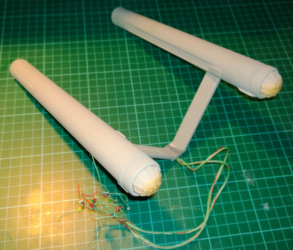
Continuing from the previous update, I needed to get the secondary hull lit.
The easy bit was to fit a strip of warm white LED in the bottom of the hull…
A quick dry fit and power up and things are looking good:
Nice natural even lighting for the windows in the main hull, however the windows in the top part of the hull that joins the saucer will need separate lighting. This is a bit more tricky as there is limited space in there for LED strip.
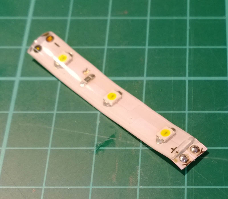
For this I decided to cut up a 3 LED section of LED strip so that I could position the LEDs exactly where I wanted them.
With LED strip lighting, you can cut the strips into sections of 3 LEDs.
The reason for this (and the reason why you can’t cut them into single LEDs) is that they are wired so that you have 3 LEDs in series with a current limiting resistor. In the picture below I’ve shown a section of 3 LEDs and have highlighted the tracks (connections) in red…
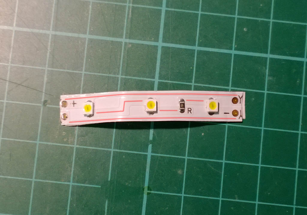
All you seasoned electrical types can look away now unless you fancy an egg to suck on, but with any electrical circuit electricity doesn’t care (for our purposes) what shape or size an electrical conductor is. A conductor can be a short flat copper track as in the LED strip shown above, or it can be a long round copper wire. This means that you can easily cut a conductor such as a copper track and join it back together with a length of copper wire in between. The only important thing is that when you re-join things together you always make sure to rejoin them the same way around so that you don’t actually change the original circuit (other than making conductors (tracks) longer or shorter).
With that in mind, I cut up the LED strip and threw away the tracks that would not be needed.
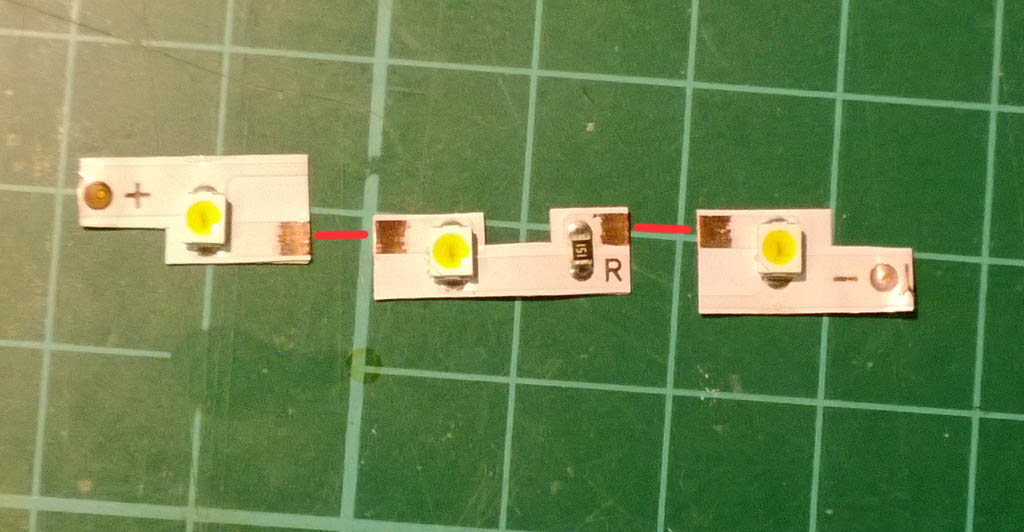
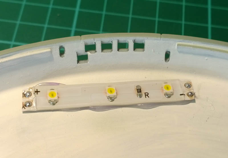
In the above photo you can see that I’ve scratched the white coating off the tracks in a few places, this is where I will be soldering on copper wires in order to re-connect them again. I’ve drawn where the wires will go in red to illustrate the circuit. In reality the wires will be longer than this and the individual LEDs will be positioned where they best illuminate the windows.
If you imagine that the red wires are actually connected for a moment, you could connect a positive supply to the left most contact marked with a “+” and connect the far right connector marked “-” to the negative supply and the LEDs would light.
The LEDs were tacked in place with blu-tack and I tweaked their positions to give me the most even lighting of the windows. As it turned out the positions of the LEDs made a massive difference to the lighting – this game is all about dry fitting and test, test, test!
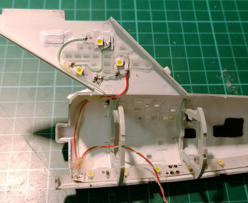
Also, you may have noticed that the lightblocking paint is no longer black in the top part of the hull. I actually found that the black paint caused dark spots in the lighting so I ended up going over it with flat white to even out the reflected light.
Once I got the positions just right, the LEDs were hot glued in place, and then wired up as can be seen. As I mentioned, electrically the modified version is exactly the same as the original strip of 3 LEDs, just that we’ve extended some of the tracks with wire.
The end result I’m really happy with:
More updates to follow in the next couple of days as I try to get this ready as a Christmas present for my wife…
Speaking of colours, due to the huge numbers of variations in paint schemes the original Enterprise had over the years I decided to work roughly towards the only two photos that I can be pretty confident are authentic.

Saying that my colours will be a bit different to above, but this is the “look’n’feel” I’m trying to achieve – very little or no weathering, and a uniform application of colour. The original enterprise needs to look a bit like a model as it was well before the days of hyper-realistic space modelling with all it’s weathering, streaking, smoking and staining ( – the streaking, smoking and staining was just the actors).
Gotta say it’s been hard to resist the urge to weather it – chip it back to aluminium, cover it in dirt and flick mud all over the front of it
24th December 2013
Well I didn’t make the Christmas deadline – it was close but in the end just not enough time to let coats of this and that cure properly before applying clear finishes so I decided not to rush the final stages.
I always find with anything creative it’s best to finish something then sleep on it and see how it looks in the morning. Unless you’re creating pies, it wouldn’t work with pies. Or a bed of nails, that wouldn’t work either. But for model making among other things a pair of fresh eyes can pay dividends, and with the secondary hull lighting I decided to leave it overnight before closing it up and found that I wasn’t quite happy with the even-ness of the lighting in the lower half.
So I fitted another strip of 3 LEDs at the top of the lower section of the hull to give a boost to the illumination down there…
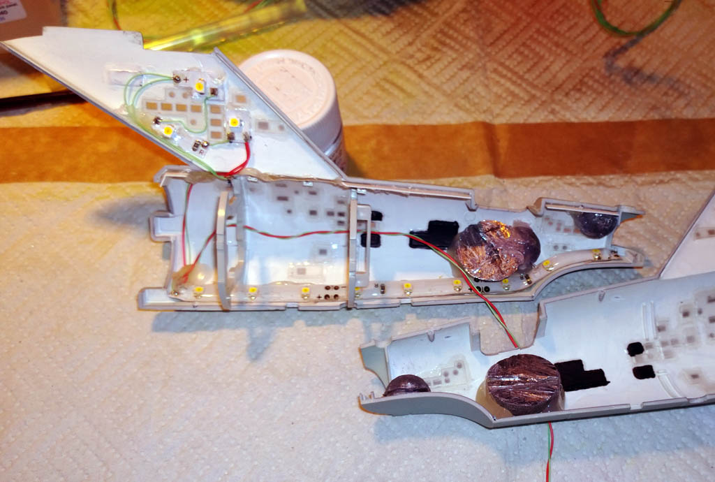
The instructions call for 90g (3oz) of weight in the back of the hull too, and with the lighting this was quite tight. I didn’t want the ballast obstructing the light so placing the weights was quite tricky. A quick sortie to the fishing tackle box produced some lead bullet weights and after a bit of hacksawing they were hot glued in place and didn’t get in the way of the light…
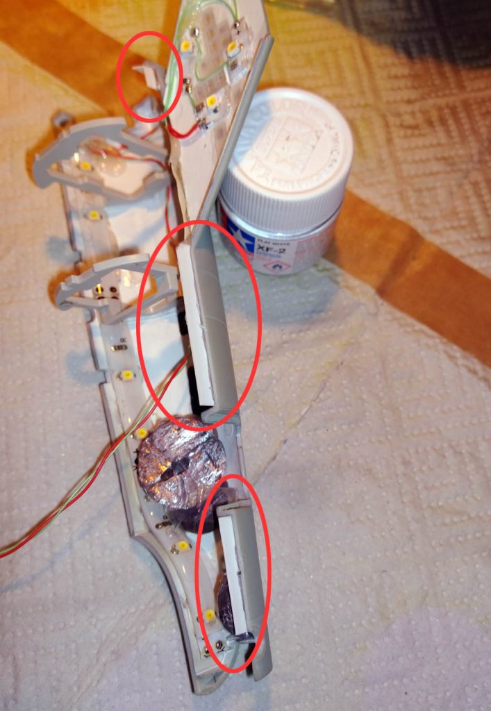
Ever paranoid about light bleed through the hull I also fitted some plasticard light baffles under the top seam to provide a physical block to the light when the hull is closed up.
You can see these better in the photo below circled in red…
I gave all the seams a good scrape with a scalpel to clean them up ready for glueing, and prepared everything to come together…
With this kit (when you light it) everything has to come together at once at the end, the saucer and engine assembly have wires that need to feed through the secondary hull and the rear hanger bay doors and front sensor need to be fitted at the same time. I usually like to work on one bit at a time, but here you have to get everything ready to rock at the same time…
After double and triple checking I hadn’t forgotten anything the time came to close up the hull and bring it all together…
So here she is, all buttoned up but nowhere to go 😉
All that remains is to fill and sand the secondary hull seams and touch the paintwork back in. But as I said, I will need to let the base coat cure for a bit before coating it with klear so won\’t be finished for tomorrow…
Not forgetting the base too… This took a bit of filling and sanding to get the seams smooth, then a coat of black gloss. The base is black and gold and I was thinking of using the technique where you paint it black, then do the gold, sealing it with Klear. Then you use a thinned mix of black over the top and rub the black off the gold with thinners to reveal the gold bit.
In the end though I decided to mask it with tape and Maskol:
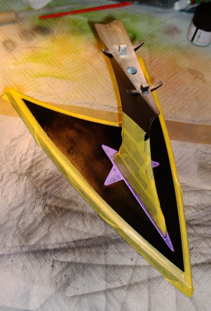
The Maskol went quite nicely into the inner star shape…
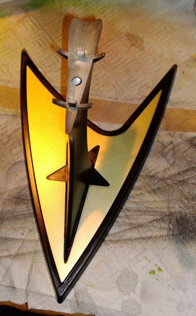
And it all came of pretty well in the end. The Maskol left a bit of a wavy line in places but overall worked really well. Will give the base a coat or three of Klear in the next day or two…
As always thanks for looking – hopefully the next update will be the final build log complete with the spinning lights and source code for the Arduino.
1st January 2014
So this is the final build log post, and with heavy heart I have no more work to do on the Enterprise. It’s been an intense build due to the self imposed deadline I put on it and I’ve enjoyed (almost) every minute of it. When we first picked the kit out in Hobbycraft a couple of months ago I thought “One rabbit stew coming right up!” (to quote Monty Python and the holy grail). How wrong was I? Fitting DIY lighting was a much bigger task than I first envisioned, not so much in terms of complexity, but in the sheer amount of preparation and tweaking that goes into getting a convincing lighting effect. Lighting is a very dynamic (almost organic) thing and doesn’t always turn out how you expect – hence it takes quite a bit of tweaking and titivating to get it looking just right.
I’ll post the final stages of the build here, and then will upload the reveal post with final photos and video later on today…
With the paintwork completed it was time to move onto decaling…
From past experience (AKA the Academy Stuka Decal Fiasco) I’ve found it best to test the decals with setting solutions before using them for real in case the decals react differently with different solutions. For this build I tested Micro-Sol, Tamiya X-20a and Solvaset using some scrap decals from the Enterprise on my trusty old MI-24 test pig.
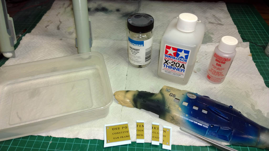
3 sections of decal were applied (with Micro-set in the water), and then from left to right I applied a good coat of Micro-sol, X-20a and Solvaset…
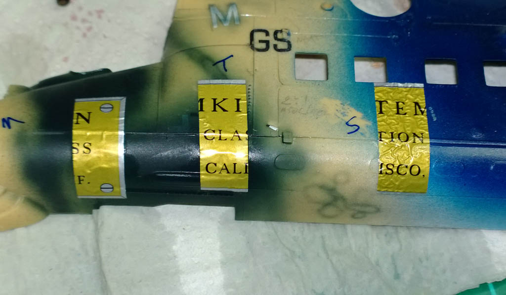
Micro-sol had the mildest action, X-20a had a bigger effect and the Solvaset was blatantly belligerent towards the decals. As you can see in the above photos the Solvaset heavily wrinkled the decal almost immediately – in the photo the various solutions have been on there for about 20 seconds.
After about an hour the decals looked as below:
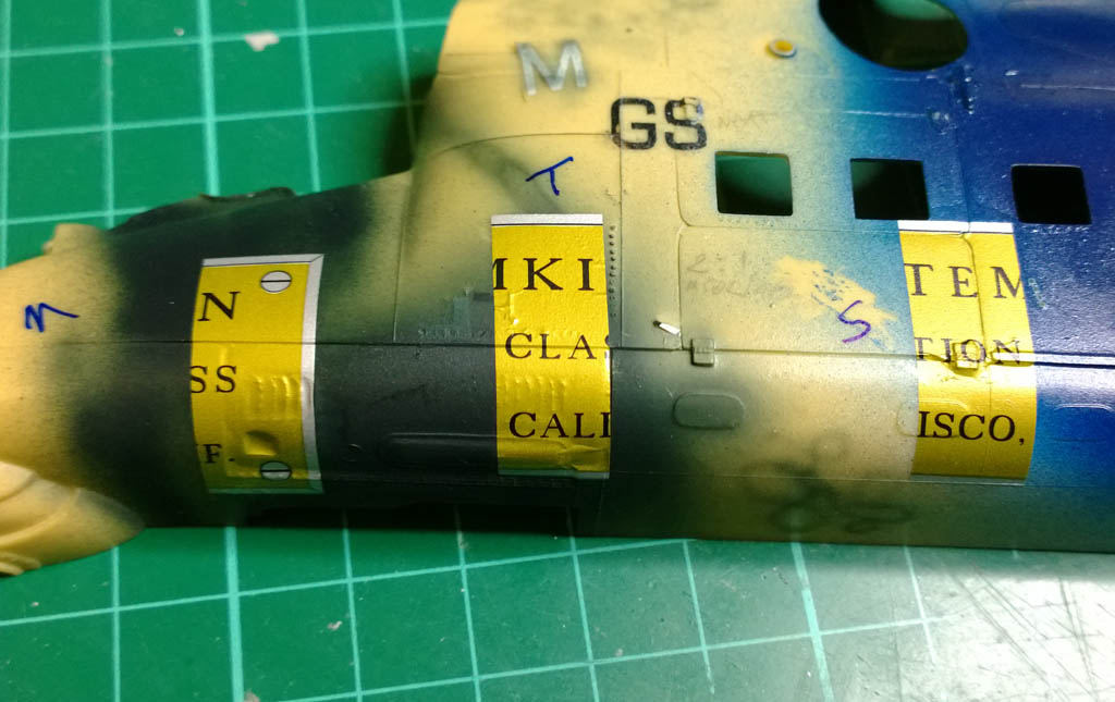
Micro-sol had the least effect, X-20a was in the middle and the Solvaset really sucked the decal down. In fact you can see that the Solvaset did such as ferocious job on the decal that the texture of the paint is showing through the decal.
Also of note is that the Micro-sol kept working for a lot longer than the X-20a, the X-20a stopped working after about 20-30 minutes but the Micro-sol kept on improving after that.
Though the Solvaset gave the strongest results, I was wary of it being so strong so opted to use Micro-sol to apply the decals to the Enterprise (I later changed my mind and went over the decals with SolvaSet)…
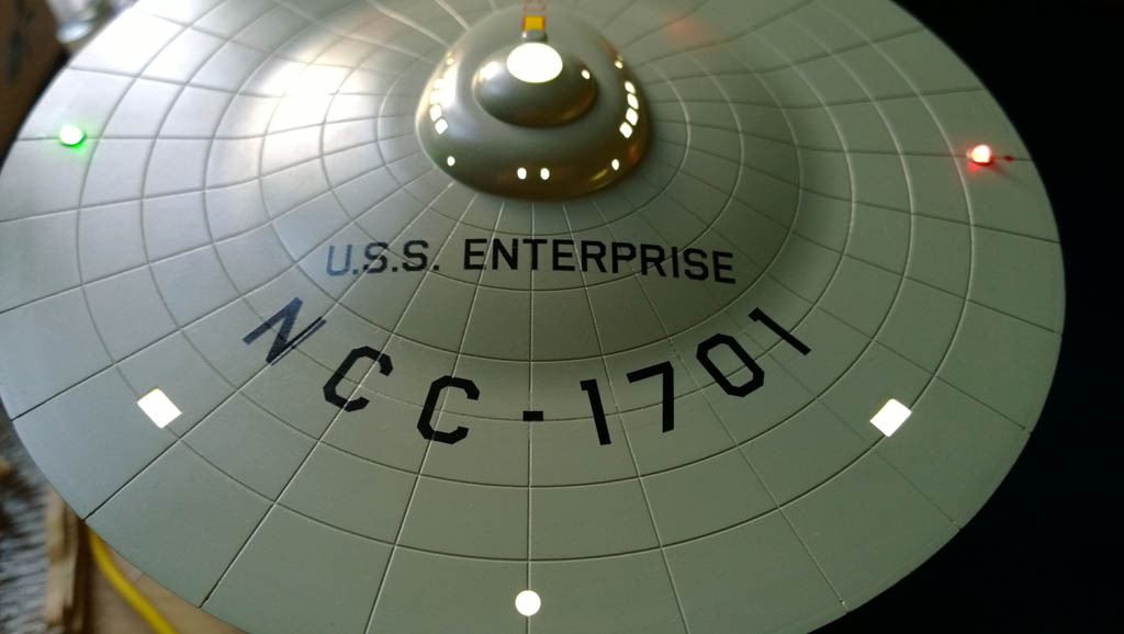
Here you can see the decals applied to the underside…
As it turned out, the Micro-sol wasn’t quite aggressive enough on the decals. They didn’t sink down into the panel lines as deep as I’d hoped and the NCC-1701 decals to the right of shot ended up very silver.
So a quick change of plan was needed and I gave the decals a good coat of Solvaset and muttered a silent prayer to the chemical gods.
One thing of note with Solvaset is that you need to apply a good coat of it – but only one coat at a time. Do it in one pass and don’t go back when the decal is wet and dabble with it. This stuff is so aggressive that the decal will soften almost immediately and if you go back and brush it again you stand a good chance of damaging the decal.
With all the decals on, a few coats of Klear were applied (Pledge wax) and left to dry for 24 hours…
Then on with the final light tweakage and wire-age…
Before I leave the realms of traditional modelling (filler and paint) I’ll just mention a few things about the hull colour…
When I first started researching this build I found a few people that swore by Tamiya XF-12 (J.N Grey) with 10% flat white added for the hull colour. it looked good to me, though I always thought the Enterprise was white – so I went along with XF-12 with 10% white.
This turned out to be a love-hate relationship, when first sprayed XF-12 looks like a light grey with a slight hint of green. When you sand the paint it looks more like a 1980’s bathroom if you remember the Avocado style colours that were popular back then? So the Greeny-grey turns into a Greyee-green.
A few other builds I’ve seen people do, they’ve gone as far as re-spraying with another colour completely, opting for a grey with no tint to it. I must say after I assembled the Enterprise I suddenly decided I no longer liked XF-12 and was close to masking the whole thing and re-spraying it with a tint free grey. However I stuck with it, and found that as I completed the decaling and final clear coats the whole effect started coming together and now the green tinge is hardly noticeable.
As you will see in the following photos (and in the final reveal) the hull colour varies greatly with ambient lighting and I think it looks great now! If I ever built another I would probably not use XF-12 again, but I reckon if you use a tint free grey i.e. just black lightened with white it would look too plain, a bit of a tint helps to give the model more dimension.
Here’s a good picture to illustrate the difficulty of painting with shades of grey:
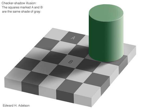
Squares A and B are exactly the same colour – I found this phenomena really kicked in with building the Enterprise, as a colour that looked one way when painted on its own looked totally different when alongside another colour.
Anyway, on with the wiring…
At this stage of the build, the microcontroller (Arduino Nano) is still outside the model on a temporary breadboard.
The breadboard allows you to simply plug components and wires in and out without soldering allowing you to rapidly prototype your circuits.
Here you can see I’ve got the Enterprise fully lit – the 12 volt hull LEDs are all on, and the engine LEDs and Nav LEDs are also on. For this build I have mounted all the LED current limiting resistors outside the kit so that I can change their values individually. Changing the value of a current limiting resistor has the effect of making the LED(s) that are attached to it brighter or dimmer. For a build like this it’s important to tweak the brightness of the LEDs as a whole – you have to see how they look all lit together and can’t just set them to a brightness and hope it works.
Lighting is such as dynamic thing to work with, and it’s also additive – in other words an LED on its own might look fine, but put another LED next to it and the light from the second LED will add to the light of the first changing the overall effect.
This was evident on the engine nacelle LEDs. Each engine has 16 LEDs in it, so if they were all run at full current (20mA) the effect would have been like having a couple of torches mounted on the model. In the end most of the LEDs were tweaked down to under 1mA to get them to dim down to a suitable intensity. To give you an example, the yellow blinking LEDs in the nacelles are run at 5V via an 8k2 resistor (which we in the trade refer to as “bugger all current”).
The hull lighting has already been tweaked (most of this was done with light baffles and positioning of the LED strips)…
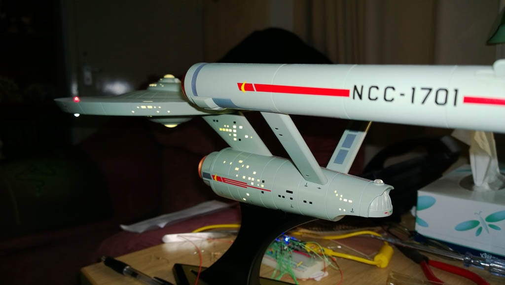
And here’s a different shade of grey for you 😉
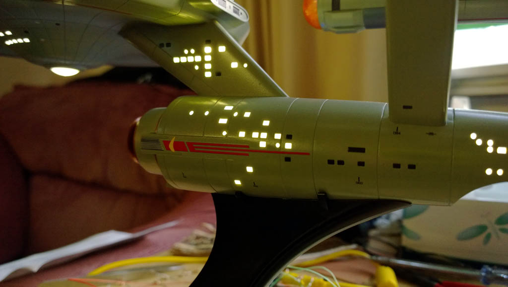
And here’s a view of the engine lighting….
The camera happened to snap this on a green phase so in reality it doesn’t look like that – you can see how it actually looks when I post the reveal video later on…
And an atmospheric of the XF-12 looking decidedly blue lol 😉
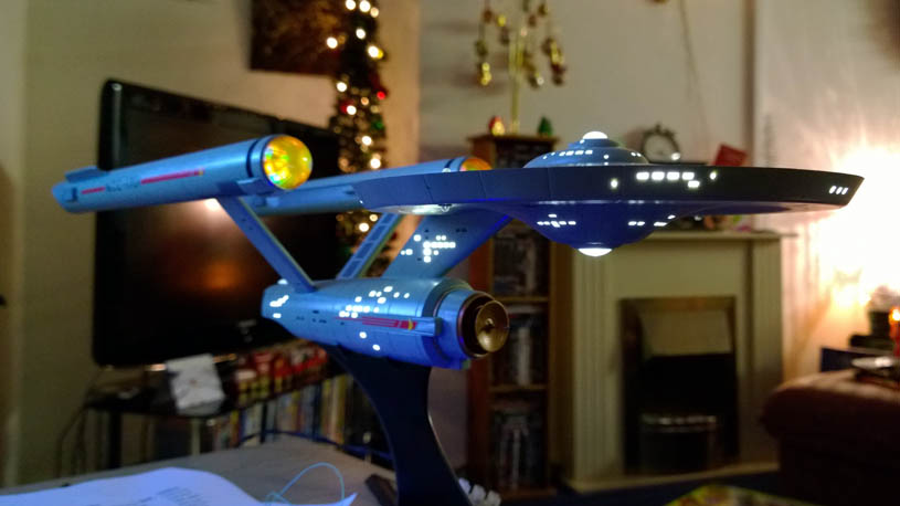
The above shot gives a much better impression of how the engine LEDs look – a pretty accurate rendition there!
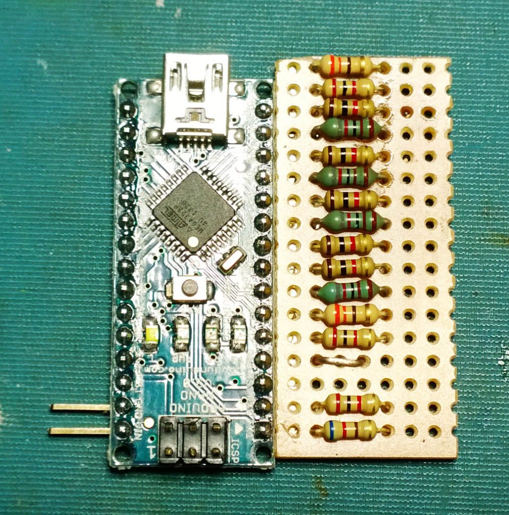
With all the LED resistors tweaked it was time to hard wire the microcontroller in place, for this I used Veroboard to allow a means of connecting to the microcontroller and also to mount the resistors themselves….
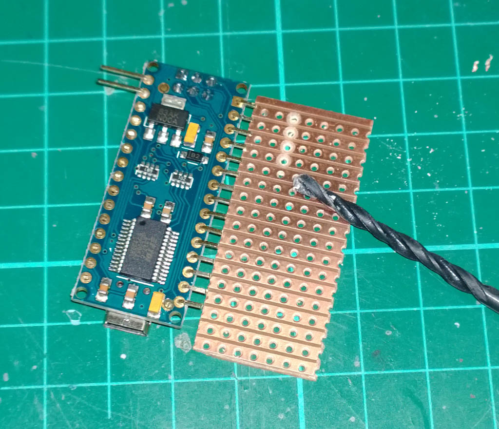
I don\’t have much vertical space in the base of the Enterprise so I nipped all the unused pins off the Arduino and bent the remaining pins through 90 degrees so they could be soldered to the veroboard.
Where the resistors will go it was necessary to cut the tracks on the veroboard, the easiest way to do this is with a 3mm drill – countersink the hole until the copper track has been cut.
Here’s the bottom view with the Arduino and resistors soldered in place:
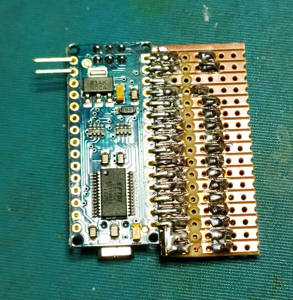
And the view from above showing the variety of resistors that have been used:
The two pins on the left are for the 12 Volt DC power supply. The beauty of the Arduino is that you can feed it 12V (which is needed to separately run the LED strips), and it will regulate the voltage down for it’s own needs and will give 5V on the output pins. Always good for reducing component count.
The finished assembly was hot-glued into the base and wired in permanently.
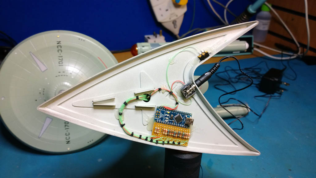
I used a 3.5 mm jack socket to get power into the base, the limitation here was height and traditional type DC jacks were all too high to fit.
Top right in the base you can see the SPST slide switch that switched the 12V DC on and off.
Also the wiring loom has been hot glued in place to keep it neatly tucked away. Hot glue is brilliant for this application as it sticks like Gorilla snot, is very strong, is very malleable so won’t crack when flexed and you can also remove it later if needs be. To be honest I wouldn’t mess around using jack posts and screws to mount components in a kit such as this, hot glue is your friend here!
Arduino Microcontrollers
The only thing that remains as far as build thread goes is to talk a little bit about the software on the Arduino…
As you will know if you\’ve been following the build so far, the lighting for this kit is controlled by an Arduino Nano Microcontroller.
The Arduino Nano can be had for about £10 on ebay and with the addition of a few external resistors can control a number of LEDs (or for that matter pretty much anything that you’d like to hook up to it). Another great thing (and there are many great things about this microcontroller) is that it is absolutely tiny and can be easily stashed inside a model, or in a small sized base.
It comes with 14 digital I/O (Input/Output) pins, so that gives you 14 different things you can switch on and off at will – more if you connect several things to each channel.
6 of the digital I/O pins can be configured as PWM, which stands for Pulse Width Modulation. Pulse Width Modulation is great because it sounds really technical and is guaranteed to impress anyone that you spout it at, but in fact it’s pretty simple stuff and means that any pin you configure to use PWM will become capable of outputting a variable current which for LEDs will allow you to control their brightness from within your code. PWM itself just means that instead of the digital I/O pin outputting a steady 5 Volts, the pin pulses on and off rapidly many times a second from 0 volts to 5 volts. The width of the pulse determines how much current the pin will deliver, a very narrow (short) pulse delivering very little current, a wide (long) pulse delivering a lot more current.
For the Enterprise lighting I didn’t use PWM, just plain old digital I/O.
The Arduino project is open source and comes with some really good (and free) development software that you can download. Once you install their software, you connect your Arduino to your PC via a USB cable (which also powers the Arduino for development purposes) and your immediately ready to start coding…
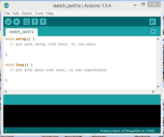
There are two main parts to the code (functions as they are known), a setup function and a loop function. You put initialisation code in the setup function, for example here you would setup how you want the various I/O (Input / Output) pins to behave. And in the Loop function you would put your code that actually does things to the pins. The loop function being repeatedly run (called) while the Arduino is powered up.
When you\’re done coding you click the Upload button as circled in red below:
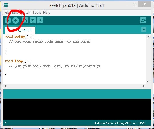
…and your program will be uploaded to the Arduino and will start running as soon as it has uploaded.
Once you have uploaded your program to the Arduino it will be stored in non volatile flash RAM in the Arduino, meaning that your program will remain stored even when the Arduino is powered off. As soon as you power up the Arduino it will automatically load your program and start running it.
Other than the actual coding, it really doesn’t get any easier than the Arduino, back in the day you used to have to build a circuit using separate chips, and programming was usually done by means of an EPROM blower which permanently (or semi-permanently) wrote your program to the chips. Programming would have been via Machine Code / Assembler and creating even the simplest of micro-control system was a job for specialists. With systems such as the Arduino, micro controllers have never been more accessible and for £10 you can be up and running in no time. (Assuming you can do a bit of coding) 😉
Arduino Programming
In terms of programming the Arduino, the good news is that you can program it in good old industry standard C. The even better news is that you can also code it in good old industry standard C++ (Pronounced “See Plus Plus”). If you are new to coding then C is a good place to start, if you’re already into coding then C++ is the better place to start.
The difference between C and C++ is that C++ is an “Object Oriented” programming language whereas C is not. C++ is a superset of C, in other words C++ has everything in it that C has plus a load of object oriented extras. I would recommend C to beginners because it will save you from having to learn all about object oriented programming – which is a major task in its own right.
With that said, the lighting control for the Enterprise has been coded to be object oriented in C++ as it makes programming multiple things (multiple LEDs) more easy. With C++ you can write a bit of code that controls a flashing LED, and then easily create multiple copies of that code for every LED that you want to control. This is trickier to do in plain old C – so the trade off with C++ is that it’s harder to learn, but easier to program when you know how.
I’ve pasted the complete source code for my Enterprise lighting at the end of this post, you’re more than welcome to copy it and modify/use it in your own projects.
The beauty of it being object oriented is that you can easily add more flashing lights by tweaking the parts labelled SECTION 1, SECTION 2, SECTION 3. All you need to do is add/remove a few lines of code and the object oriented part will handle the functionality for you – you won’t need to touch that part of it.
Rich\’s Enterprise Lighting Controller Code…
For my project I have two separate parts of the kit to animate with light, the navigation lights on the saucer and the engine nacelle lights…
The nav lights are simply 4 LEDs that flash on and off on a regular period. No problem there, just need to turn on the LEDs for 1500mS and then turn them off for 450mS.
The engines are somewhat more complex, for each of these I have a ring of 12 LEDs that will operate on a chaser circuit whereby groups of 3 LEDs will be cycled in sequence to make it appear that they are chasing round in a circle. In the middle of this will be 4 LEDs that randomly blink on and off.
The main problem typically faced when programming multiple things to happen at once on any kind of computer is that computer programs typically tend to only do one thing at a time. So if you turn on an LED and then wait 1500mS before turning it off again by using the built in delay functions, the computer (Arduino in this case) will be busy doing nothing waiting for 1500mS. It won’t be able to do anything else until the 1500mS has elapsed, giving the impression that it has hung. That’s no good here because we want the Arduino to be chasing 24 chaser LEDs, randomly blinking 8 engine LEDs and steadily flashing 4 nav LEDs all at the same time.
What I ended up doing was to create a piece of code (called a “class”) to represent the chaser circuit, and also another class to represent the flashing LEDs. The chaser class handles all the functionality required to chase LEDs in a circle, while the FlashingLED class knows how to handle LED flashing.
To get around the ‘one thing at a time’ limitation what we do is to create a service function within each class. When we call the service function (from the Arduino loop) the object (flashing LED or chaser) works out how much time has elapsed since it last changed state (e.g. from on to off), and if it is time to change again it makes the required change. This means that we don’t have to delay anywhere in our code, we just wizz around calling the service function of each object in rapid succession. This doesn’t actually allow two things to happen at once, but it gives the impression that multiple things are happening at the same time. In effect the objects are serviced in succession so quickly that the human eye would not be able to see that in fact things are happening one after the other.
For the chaser I just create a single chaser object, whereas for the flashing LEDs I create multiple FlashignLED objects, one for each flashing LED. Again this is the beauty of object oriented programming – I wrote the code for a FlashingLED and then when I need flashing LEDs I just create a separate instance or copy of the flashing LED for each one.
All of the information that an object needs is passed to it when it is created, so for a flashing LED we create it and pass it which Arduino channel number it should use, how long it should stay off for, and how long it should stay on for. For example:
navLED12 = new FlashingLED(12, 450, 1500);
The above line creates a new flashing LED object that will flash digital output 12 to be off for 450mS and on for 1500mS. We\’ve also got a more advanced method of constructing a flashing LED object as per the following example:
portEngineLED11 = new FlashingLED(11, 600, 2200, 40, 400);
The above line also creates a flashing LED, but this time for digital output 11 to randomly flash. The LED will be off for between 600 and 2200mS, and will be on for between 40 and 400mS.
Here’s the final source code that I ended up using, as I said feel free to grab a copy if it will help you. Also please feel free to post any questions you have here and I’d be happy to try and answer them…
|
1 2 3 4 5 6 7 8 9 10 11 12 13 14 15 16 17 18 19 20 21 22 23 24 25 26 27 28 29 30 31 32 33 34 35 36 37 38 39 40 41 42 43 44 45 46 47 48 49 50 51 52 53 54 55 56 57 58 59 60 61 62 63 64 65 66 67 68 69 70 71 72 73 74 75 76 77 78 79 80 81 82 83 84 85 86 87 88 89 90 91 92 93 94 95 96 97 98 99 100 101 102 103 104 105 106 107 108 109 110 111 112 113 114 115 116 117 118 119 120 121 122 123 124 125 126 127 128 129 130 131 132 133 134 135 136 137 138 139 140 141 142 143 144 145 146 147 148 149 150 151 152 153 154 155 156 157 158 159 160 161 162 163 164 165 166 167 168 169 170 171 172 173 174 175 176 177 178 179 180 181 182 183 184 185 186 187 188 189 190 191 192 193 194 195 196 197 198 199 200 201 202 203 204 205 206 207 208 209 210 211 212 213 214 215 216 217 218 219 220 221 222 223 224 225 226 227 228 229 230 231 232 233 234 235 236 237 238 239 240 241 242 243 244 245 246 247 248 |
/* LEDFlasher ========== Created 9th December 2013 by -=Richard Moore=- richard@easify.co.uk ========================= This code is in the public domain and you are free to copy it, modify it and re-distribute it as you see fit. All I ask is that you keep the above credits in the header intact. ============================================================================ This code consists of two classes that allow you to flash multiple LEDs without the need for using the delay() function. The code was originally written to control the DIY lights I made for a Revell 1/600 scale Star Trek USS Enterprise TOS (The Original Series). The engine nacelle lights are driven by the Chaser class which handles stepping a ring of LEDs, and an LEDFlasher class handles a few flashing engine lights and also the flashing navigation lights on the saucer. Chaser class ============ When you create this class you pass it the Arduino pin numbers that you want to connect your chaser LEDs to, I've named them yChannel, rChannel, gChannel and bChannel (Yellow, Red, Green, Blue). Also pass in the chaseSpeed which is the delay in mS between each step of the chaser. From the main loop call the Chaser->Service() method on each pass to service any pending LED sequence changes. FlashingLED class ================= This class allows you to have multiple flashing LEDs that do not depend on the delay() function for their timing. This means they can all be processed simultaneously and will also work alongside the Chaser class. There are two types of LEDs you can create, fixed period and random period. Call the FlashingLED constructor with Channel number, off time and on time to create a fixed period LED which will flash the chosen channel at the fixed time period specified. To create a random flashing LED, call the FlashingLED constructor with channel number, minimum off time, maximum off time, minimum on time and maximum on time to create a flashing LED with a random time period. The LED will be off for between minOffTime and maxOffTime mS, and will be on for between minOnTime and maxOnTime mS. From the main loop call the FlashingLED->Service() method on each pass to service any pending LED state changes. */ /* Chaser class */ class Chaser { private: int timePeriod; int yellowChannel, redChannel, greenChannel, blueChannel; int chaserState; long lastTimeCount; public: Chaser(int yChannel, int rChannel, int gChannel, int bChannel, long chaseSpeed){ yellowChannel = yChannel; redChannel = rChannel; greenChannel = gChannel; blueChannel = bChannel; pinMode(yellowChannel,OUTPUT); pinMode(redChannel,OUTPUT); pinMode(greenChannel,OUTPUT); pinMode(blueChannel,OUTPUT); timePeriod = chaseSpeed; chaserState = 0; lastTimeCount = millis(); }; void Service() { // See if it is time to step the chaser... if (millis() >= lastTimeCount + timePeriod) { // Chase the LEDs around another step... lastTimeCount = millis(); switch(chaserState){ case 0: // Yellow digitalWrite(blueChannel, LOW); digitalWrite(yellowChannel, HIGH); chaserState += 1; break; case 1: // Red digitalWrite(yellowChannel, LOW); digitalWrite(redChannel, HIGH); chaserState += 1; break; case 2: // Green digitalWrite(redChannel, LOW); digitalWrite(greenChannel, HIGH); chaserState += 1; break; case 3: // Blue digitalWrite(greenChannel, LOW); digitalWrite(blueChannel, HIGH); chaserState = 0; break; }; }; }; }; /* FlashingLED Class */ class FlashingLED { private: long minOffTime, maxOffTime; long minOnTime, maxOnTime; long offTime, onTime; bool ledIsOn; long lastTimeCount; int channel; void RegenerateTimes(){ // This is called to re-calculate the off and on times for the LED. If the min and max times // are the same then the LED will always flash with the same period i.e. not random. offTime = random(minOffTime, maxOffTime); onTime = random(minOnTime, maxOnTime); }; public: //TODO: Somehow add ability for delayed start i.e. start flashing sequence after fixed or random delay... FlashingLED(int channelNo, long offTime, long onTime){ // Call this constructor to instantiate a simple flashing LED channel = channelNo; pinMode(channel,OUTPUT); this->minOffTime = offTime; this->maxOffTime = offTime; this->minOnTime = onTime; this->maxOnTime = onTime; RegenerateTimes(); ledIsOn = false; lastTimeCount = millis(); }; FlashingLED(int channelNo, long minOffTime, long maxOffTime, long minOnTime, long maxOnTime){ // Call this constructor to instantiate a flashing LED with a random off time and random on time channel = channelNo; pinMode(channel,OUTPUT); this->minOffTime = minOffTime; this->maxOffTime = maxOffTime; this->minOnTime = minOnTime; this->maxOnTime = maxOnTime; RegenerateTimes(); ledIsOn = false; lastTimeCount = millis(); }; void Service(){ // See if it time to turn on/off the LED if (ledIsOn) { // LED is ON if (millis() >= lastTimeCount + onTime){ lastTimeCount = millis(); digitalWrite(channel, LOW); ledIsOn = false; RegenerateTimes(); }; } else { // LED is OFF if (millis() >= lastTimeCount + offTime){ lastTimeCount = millis(); digitalWrite(channel, HIGH); ledIsOn = true; RegenerateTimes(); }; }; }; }; /* SECTION 1 - INSTANCE DECLARATIONS For each object (thing) that you want to implement, create an instance of it here... */ Chaser *chaser; FlashingLED *stbdEngineLED4; FlashingLED *stbdEngineLED5; FlashingLED *stbdEngineLED6; FlashingLED *stbdEngineLED7; FlashingLED *portEngineLED8; FlashingLED *portEngineLED9; FlashingLED *portEngineLED10; FlashingLED *portEngineLED11; FlashingLED *navLED12; void setup() { // put your setup code here, to run once: // Make the random number generator be random randomSeed(analogRead(0)); /* SECTION 2 - INSTANTIATE THE OBJECTS For each object (thing) that you declared in SECTION 1, you will need to instantiate it (initialise it) here...*/ // Initialise chaser... chaser = new Chaser(2, 3, 1, 0, 22); // Initialise flashing LEDs... stbdEngineLED4 = new FlashingLED(4, 400, 2500, 10, 150); stbdEngineLED5 = new FlashingLED(5, 500, 2000, 40, 380); stbdEngineLED6 = new FlashingLED(6, 600, 2500, 40, 385); stbdEngineLED7 = new FlashingLED(7, 600, 2200, 40, 400); portEngineLED8 = new FlashingLED(8, 400, 2500, 10, 150); portEngineLED9 = new FlashingLED(9, 500, 2000, 40, 380); portEngineLED10 = new FlashingLED(10, 600, 2500, 40, 385); portEngineLED11 = new FlashingLED(11, 600, 2200, 40, 400); // Saucer nav LEDs navLED12 = new FlashingLED(12, 450, 1500); } void loop() { // put your main code here, to run repeatedly: /* SECTION 3 - Service your objects... For each object that you have declared and instantiated, you will need to call its 'Service()' method here...*/ chaser->Service(); stbdEngineLED4->Service(); stbdEngineLED5->Service(); stbdEngineLED6->Service(); stbdEngineLED7->Service(); portEngineLED8->Service(); portEngineLED9->Service(); portEngineLED10->Service(); portEngineLED11->Service(); navLED12->Service(); } |
26th January 2016
Captain’s (build) log, star date January 2016…
Since finishing this build log I’ve had quite a few questions about the wiring details for it.
So retrospectively I’ve taken a bit of time out to put together a wiring diagram that should (at least) give you an idea of how I went about wiring her up…
Now, the following wiring diagram may not be 100% accurate as I have had to reverse engineer it from my notes but as I will elaborate in a while, this kind of wiring is more an art form than pure science. So if a few resistor values have been swapped around in translation it won’t matter… Some of your LEDs might just end up a bit bright (or dim).
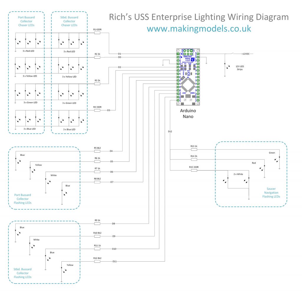
The above diagram is 1920 pixels wide, so you can click it to view it full size.
You might also find the following diagram useful, this is the diagram I used during the build to help me keep track of which LED goes in which hole in the Bussard Collectors…
Going back to what I was saying about this kind of electronics being more art than science…
There are lots of online sources about LED resistor calculations and i\’s easy to get caught up in the science and believe that you need to exactly calculate voltage drops and forward currents and take into account reverse biases and all kinds of parameters in order to light up a LED. Well the simple truth is that you don’t.
My advice when working out resistor values for LEDs is to use a basic bit of maths (yep a little bit of Ohm’s Law) and then trust to eye for the final tuning.
What I mean is this: The output from an Arduino pin is 5 Volts. Most LEDs have a maximum forward current of 20mA.
That is 0.02 Amps.
What this means is that if you allow the LED to draw more than 0.02 Amps (20mA) it will blow up.
Which is bad.
Without a resistor to limit the current, an LED connected straight to a power supply will attempt to draw (almost) infinite current and will destroy itself trying. To prevent this we put a resistor in line with the LED (in series) which will limit the current the LED can draw (current limiting resistor).
So what value resistor do you need to use?
I said that a typical LED can be allowed to draw up to 20mA before it goes pop, so if we use Ohm’s law to work out the resistance required to limit 5 Volts (the voltage on an Arduino pin) to a maximum current of 20mA we get 250 Ohms.
R = V/I
250 = 5/0.02
So in a nutshell, a 250 Ohm resistor in series with a single LED will limit the current that the LED can draw to about 20mA.
Here is where the art comes into it…
With a model such as the USS Enterprise, you’re not going to want the LEDs to draw their maximum current otherwise they will be like (freakin’) lasers and will be so bright as to cause arc-eye.
No, for modelling purposes you will want the LEDs to be dimmed down somewhat so that they look right.
Also bear in mind that different LEDs all give a different light output (brightness) for a given current. So for the same current a red LED could be twice as bright as a green LED (or vice versa).
Therefore the best and easiest approach is to start out with resistors of 250 Ohms (or more) and see how the LEDs look when illuminated. If you have an LED that is way too bright, swap the resistor for a higher one. I’d start at 1k (1,000 Ohms) for an LED and see how it looks. If it is too bright try 2k, too dim then try 500Ohms.
As long as you don’t go below 250 Ohms you will be fine. Anything higher than 250 Ohms will lower the current and the LED will be dimmer.
You will note that some of the Arduino channels in my diagram drive multiple LEDs. In this case the current will be shared by all the LEDs on that channel so you will need to reduce the value of the resistor to allow more current through. Even so, the lowest resistance I used was 330 Ohms to drive six LEDs – which is approx. 15mA for all LEDs or about 2.5mA each.
This is another reason why I situated the LEDs outside the body of the model, it allowed me to see how the lighting looked in the finished model and do any final teaks to the resistor values with no problem. If you put the resistors close to the LEDs and entomb them in the model you will have difficulty in changing the brightness of the LEDs.
I hope this extra info is useful, let me know in the comments below if you have any more questions.
Congratulations if you managed to follow my USS Enterprise build log this far, I hope you had as much fun reading it as I had doing it!


61 thoughts on “Illuminated 1/600 Revell USS Enterprise – Star Trek the Original Series – Build Log”
Fantastic work on this build. I bought the same model and ran across this and your YouTube video while looking for ideas on lighting it up.
Well done!
Thanks Blaine, I had great fun building it. Good luck with your build 🙂
Following a liver transplant I was stuck with additional hobby time and my kids bought me the Enterprise 350 and a F14 Tomcat. Following a search I came across your site and it drove me on to rekindle my youth and have a go at doing it your way with lights, fillers, proper paint job, rather than just sticking it together!
Excellent and highly informative. I’m even looking for the Maverick and Goose look as the Final Countdown was the first movie my wife and I ever saw together!
Keep it up!
Thanks Kevin, glad you found the info interesting. Good luck with your Enterprise and Tomcat 🙂
That’s very nice of you; she will love you evwn more for it. I’ve done models, mostly classuc cars and WWII aircraft. Even though I’m a Trekkie I have never done what you’re attempting to do. 1)Where did you get this particular kit?
2)Lighting kit? Didn’t know those existed! Where from? Feel free to use my email, because I would really like to now. Thank you!
I bought the kit in Hobbycraft in the UK, but it’s a readily available kit. You could pick one up online with no trouble.
The lighting kit I made myself, have a read through the build log – there are 12 pages where I give a step by step guide through the process.
Let me know if you have any other questions.
Hello Mr,Moore. If I may ask a few more question I would be very grateful. I see that you managed to connect 32 leds with only 9 wires ? Do you have any schematic you could share or something.
Thanks and best regards.
I run more than one LED per Arduino output.
So for example the Yellow LEDs in the chaser in the Bussard Collectors there are 3 yellow LEDs in the starboard side, and 3 yellow LEDs in the port side. All 6 yellow LEDs are fed from a single Arduino pin.
Same with the saucer navigation LEDs, here all 4 navigation LEDs are fed from a single Arduino pin.
Electrically speaking, I feed the output from an Arduino pin through a single resistor, and the output from the resistor gets split off to the LEDs that need to be fed from it. This means you don’t have to include a current limiting resistor for every LED.
I have some documents that I put together that show some of the wiring connections (wiring schedule), but I don’t have a full schematic. Give me a few days and I will see if I can collect what info I do have on paper and I’ll see if I can put it on an additional page in the build log.
Oh I see. Somwhere I read that Arduino output gives 40mA, is that ok for 6 LEDs ?? Thanks for schematic, take your time 🙂
The Arduino Nano does give 40mA per pin, but I found that the LEDs didn’t need anywhere near their full current to be the correct brightness.
If you look at the photo of the resistors I used (second from last photo here http://www.makingmodels.co.uk/builds-in-progress/1600-revell-uss-enterprise-star-trek-the-original-series-build-log/11/) the smallest resistance I used was 1k. So 5V / 1k = 2.5mA. So the most current I draw for a pin is 2.5mA, and for the 6 x yellow LEDs I believe they are hooked onto a single 2.2k resistor so they are getting about 0.4mA each.
Something else to bear in mind with the Arduino Nano is that although it’s rated 40mA per pin, the *TOTAL* combined I/O current cannot exceed 200mA. Not relevant to this build, but worth bearing in mind 😉
I see. Thank you. Very helpful 🙂
Hi Goran, have added a new page to the build log complete with schematic. http://www.makingmodels.co.uk/builds-in-progress/1600-revell-uss-enterprise-star-trek-the-original-series-build-log/13/
I have bought flickering leds, do you think it will be a problem ?? Should I buy regular leds ??
They should work Ok, you could try them on a test circuit and see how they look. If you don’t like the effect they give buy some regular LEDs.
Thank you very much. I couldn’t do it without help. I will start to work on connecting circuit and I will need some help when i get to Arduino proggraming part, not quite get it, so I hope you will have some time in thr future to explain a little 🙂
Good luck with your Build – any questions you know where to come 🙂
Hello Richard, I am back with some new questions 🙂 I decided to go with this solution. I will use 4 LED’s in the saucer, and 8 LED’s in each of bussard. In the bussard i will have 2 LED’s for each of this color – red, yellow, blue, green. The pair of each color will blink simultaniously, and then next color will blink xx time later, like it goes around in circle. I wanted to connect like this, 4 LED’s on the one pin, like 4 red LED’s from bussards to pin no.1, then 4 green LED’s to pin no.2 and so on. I hope you got the idea. What do you think about this, and is there any way you could help me a little bit with arduino programming, because I am not so good with programming, thank you.
Sounds fine Goran, that’s pretty much how I wired mine. For example, the red LEDs of the left and right Bussard Collector were wired to the same pin on the Arduino.
If you use my code as listed here – http://www.makingmodels.co.uk/builds-in-progress/1600-revell-uss-enterprise-star-trek-the-original-series-build-log/12/ it will drive the Bussard chasers for you – they connect to outputs D0-D3.
Let me know if you need any help with the code.
Hello Richard, I think that I understand this code pretty well. For CHASER class I don’t need to change anything because I will use four colors like you, only I will use two LED’s per color. My question is for this flashing LED’s. I would like to know what part of FLASHINGLED class I need only to power 4 navigation LED’s in the saucer ?? I won’t have flashing led’s in the bussards.
And finnaly in my case I only need this in last part of the code ? Am I right ?
void loop() {
// put your main code here, to run repeatedly:
/* SECTION 3 – Service your objects…
For each object that you have declared and instantiated, you
will need to call its ‘Service()’ method here…*/
chaser->Service();
navLED12->Service();
}
That’s right, you can use the same chaser code and connect your Bussard chaser LEDs to the same Arduino outputs that I did.
The saucer Nav LEDs are initialised as follows:
// Saucer nav LEDs
navLED12 = new FlashingLED(12, 450, 1500);
This means that Arduino pin D12 is flashed off for 450mS and on for 1500mS. You can just connect your saucer nav LEDs to Arduino pin D12 if you use my code.
For SECTION 3 you are correct, you just need to service the chaser and navLED12.
So code for my case would be like this:
class Chaser
{
private:
int timePeriod;
int yellowChannel, redChannel, greenChannel, blueChannel;
int chaserState;
long lastTimeCount;
public:
Chaser(int yChannel, int rChannel, int gChannel, int bChannel, long chaseSpeed){
yellowChannel = yChannel;
redChannel = rChannel;
greenChannel = gChannel;
blueChannel = bChannel;
pinMode(yellowChannel,OUTPUT);
pinMode(redChannel,OUTPUT);
pinMode(greenChannel,OUTPUT);
pinMode(blueChannel,OUTPUT);
timePeriod = chaseSpeed;
chaserState = 0;
lastTimeCount = millis();
};
void Service()
{
if (millis() >= lastTimeCount + timePeriod)
{
lastTimeCount = millis();
switch(chaserState){
case 0: // Yellow
digitalWrite(blueChannel, LOW);
digitalWrite(yellowChannel, HIGH);
chaserState += 1;
break;
case 1: // Red
digitalWrite(yellowChannel, LOW);
digitalWrite(redChannel, HIGH);
chaserState += 1;
break;
case 2: // Green
digitalWrite(redChannel, LOW);
digitalWrite(greenChannel, HIGH);
chaserState += 1;
break;
case 3: // Blue
digitalWrite(greenChannel, LOW);
digitalWrite(blueChannel, HIGH);
chaserState = 0;
break;
};
};
};
};
Chaser *chaser;
FlashingLED *navLED12;
void setup() {
chaser = new Chaser(2, 3, 1, 0, 22);
navLED12 = new FlashingLED(12, 450, 1500);
}
void loop() {
chaser->Service();
navLED12->Service();
}
Or did I missed something ??
You will still need the FlashingLED class to flash the saucer nav lights:
/* FlashingLED Class */
class FlashingLED
{
private:
long minOffTime, maxOffTime;
long minOnTime, maxOnTime;
long offTime, onTime;
bool ledIsOn;
long lastTimeCount;
int channel;
void RegenerateTimes(){
// This is called to re-calculate the off and on times for the LED. If the min and max times
// are the same then the LED will always flash with the same period i.e. not random.
offTime = random(minOffTime, maxOffTime);
onTime = random(minOnTime, maxOnTime);
};
public:
//TODO: Somehow add ability for delayed start i.e. start flashing sequence after fixed or random delay…
FlashingLED(int channelNo, long offTime, long onTime){
// Call this constructor to instantiate a simple flashing LED
channel = channelNo;
pinMode(channel,OUTPUT);
this->minOffTime = offTime;
this->maxOffTime = offTime;
this->minOnTime = onTime;
this->maxOnTime = onTime;
RegenerateTimes();
ledIsOn = false;
lastTimeCount = millis();
};
FlashingLED(int channelNo, long minOffTime, long maxOffTime, long minOnTime, long maxOnTime){
// Call this constructor to instantiate a flashing LED with a random off time and random on time
channel = channelNo;
pinMode(channel,OUTPUT);
this->minOffTime = minOffTime;
this->maxOffTime = maxOffTime;
this->minOnTime = minOnTime;
this->maxOnTime = maxOnTime;
RegenerateTimes();
ledIsOn = false;
lastTimeCount = millis();
};
void Service(){
// See if it time to turn on/off the LED
if (ledIsOn)
{
// LED is ON
if (millis() >= lastTimeCount + onTime){
lastTimeCount = millis();
digitalWrite(channel, LOW);
ledIsOn = false;
RegenerateTimes();
};
}
else {
// LED is OFF
if (millis() >= lastTimeCount + offTime){
lastTimeCount = millis();
digitalWrite(channel, HIGH);
ledIsOn = true;
RegenerateTimes();
};
};
};
};
Insert this above the line that reads:
Chaser *chaser;
Got it, thank you 🙂
Hello Richard. Today i connected my first bussard to arduino to test program. It’s working fine.
Can you please watch this video – https://www.youtube.com/watch?v=-kE0fYvoG8k
Do you thinh that flashing is too fast, should I slow it a little bit ??
Looking good Goran, I’d say that’s about right. You can always tweak the code after the model is finished if you need to.
Ok, and if I want to slow them down a litle bit, where in the code would I do that ? Thanks.
Find this line of code:
chaser = new Chaser(2, 3, 1, 0, 22);
Replace 22 with a higher number. Doubling the number would half the speed.
Hello Richard, if I may ask, how did you manage wires from bussards on picture 5, page 8. Did you drill hole in the middle of this part that connects bussards or ? Thank you.
Have a look at photo 2 on page 9. It was a case of cutting away the plastic just enough for the wires to make it through. Definitely pays to use thin wire!
Hi Richard, I’ve just been given the 1/600 NCC1701 and after much trawling through the internet finally came across your very interesting take on the wiring solution.
I am a complete newbie with regard to electronics, coding, soldering and well… just about everything really, I do intend to do some smaller projects first however but I thought it would be a challenging exercise to help develop some new skills. I do have a question about the wiring diagram and the earth symbols after each array; do they return to the Arduino GND pin if so which one as I believe there are two, and are they grouped as one loom? please excuse if this is an obviously easy question or just plain stoopid.
Hi Mark,
No such thing as a stupid question – the only stupid question is one that isn’t asked 😉
On a circuit diagram instead of drawing every ground wire it’s much better for clarity just to show the ground symbol. It saves lots of clutter and extra detail that isn’t needed. All you need to assume is that every ground is (somehow) connected to every other ground. So when it comes to the actual wiring you would put a physical ground wire connecting all the ground points (where the ground symbols are).
In terms of the Arduino ground, I can’t remember if I connected both Arduino ground pins, but you’d probably find that the two pins are connected on the Arduino circuit board anyway which means you wouldn’t have to ground both of them.
Fire away if you have any other questions and good luck with your builds 🙂
Hi Richard!
My name is Keith & I live in Louisiana, USA. I have been studying your awesome build of the Original Series Revell Enterprise. Know you have heard this many times, but….WOW! You did such an amazing job on the building AND the documentation of this model project. My hat is off to you, sir!!! I have purchased the same kit & have rounded up most of what I will need to put her together. I am planning on having the engine nacelle fans rotate via some small DC motors. Also will have LEDs in them of course, though I’m probably only going to have about 8 or so in each. Anyway, I’ll get to the point, (if there is one!?). Do you think I can drive all the LEDs & the motors with a single Arduino Nano or such? Or would it require two? Any thoughts or suggestions would be greatly appreciated!
Thanks so much for your time!
Hi Keith, thanks for posting here – much appreciated 🙂
A single Arduino could handle 8 LEDs no problem at all. Regarding the motors it would depend on what current the motors will draw.
If I were you I wouldn’t drive the motors from the Arduino because AFAIK the motors will just need to run at a constant speed and will either be on or off (it’s the LEDs that will flash on and off). So probably best to just wire the motors onto the main power supply and not through the Arduino.
If you do decide to connect the motors to the Arduino, I’d recommend not directly connecting them to the Arduino outputs but instead connect them via a driver transistor. 2 reasons for this: 1) The driver transistor will be what provides the current to the motor, so you won’t be limited to the maximum output current of an Arduino pin. 2) Since motors are inductive loads they can induce a reverse current into their source (back EMF) – this might damage a micro controller so better to have the motor isolated from the chip via a driver transistor.
HTH – Rich
Hi Rich,
I will take all that into account. Thanks so much!!
Keith
Feel free to comment if you have any other questions Keith – good luck with your build 🙂
Hi, Richard. I have a favor to ask if you could help me. I am trying to buy a plastic box for the stand of my Enterprise, but I don’t know what are dimension of this included stand ? I won’t be able to get to my model few more days, and I need that info like yesterday 🙂 If you have your model somewhere around you, could you post dimensions of the stand (only vertical part that has shape on star trek logo) thanks 🙂
Hi Goran, the height of the vertical part of the stand is 100mm from the top of the base plate to the top of the highest part of the vertical part of the stand. Does that help?
Thank you Rich, very helpful
we completed the same model with arduino and leds, we just added a pulsating led light on the tail
http://www.youtube.com/watch?v=8qbS6Jo9Wrk
You did a fantastic job Manuele, thanks for sharing the excellent video!
Hello,
I found your build log amazing! Please can you share your paint chart for this build? I don’t want to use Revell paint so I want to follow your lead by using Tamiya paint instead.
Please can you share info?
Thank you very much
Hi Diego,
The external colour was Tamiya XF12 J.N Grey with 10% Flat White, this looks good but I would use a different colour if I did another one as this colour has too much of a green tint to it.
If you go to page 11 of the build log, I mention more about the external colour choices.
http://www.makingmodels.co.uk/builds-in-progress/1600-revell-uss-enterprise-star-trek-the-original-series-build-log/11/
I love the work you did on this build. I know you’re not crazy about the tamiya xf12 with 10% white, but I think it looks great. I was wondering though, you never mentioned whether you added thinner or not. Did you? And how much? And what airbrush did you use? Thanks. Keep up the great work.
Hi Gordon,
I must admit I’m really happy with the end result but would aim to reduce the green tint if I did one again.
When I spray Tamiya acrylics I always thin it very heavily probably 30% paint to 70% thinners (X-20a). This way I can build up many coats of paint gradually, and the end result is very smooth and free from orange peel effect.
My airbrush of choice is the Harder & Steenbeck Evo 2 in 1 with a 0.2mm needle. It’s a great all rounder for modelling and very easy to clean.
Cheers – Rich
Thanks for the info. I really appreciate it.
Any time Gordon, any more questions feel free to fire away.
Actually one more question. You said 70% x20a. I ordered 1 bottle of 23ml xf12, 1 bottle of 23ml xf2, and 2 bottles of the x20a thinner 46ml each. Will that be enough? Thanks again
I used about one and a half 10ml bottles of XF12, so 1 23ml bottle should be enough.
Thanks
Hi Rich,
Thank you for your explanation about the paint. Much appreciated.
I have one more question about the painting. What painting did you use for Engine nachelle’s back end/”exhaust cover” (for want of a better word). It looks like you use same paint on it as intercooler interior (stainless steel paint?). If it is not the case, please can you tell us which grey paint (of Tamiya) did you use on Exhaust cover/back end of nachelle.
Finally, I was reading Page 7 of Build log and I was a bit unclear on 2nd last paragraph on that page. Shouldn’t it be 32 LEDs and 10 wires running into the microprocessor?
Thank you again
Diego
Hi Diego,
The round domed bit at the back of the nacelles was done in a very light grey, could have been XF-80 Royal Light Grey with a bit of added white. The bit that the round domed bit attaches onto was painted with XF-66 Light grey.
In the photo on Page 7, there are 16 LEDs per side which is 32 pins. The outer ring has 4 groups of 3 LEDs (4 wires since I connect all 3 of a similar colour using the same wire) and there are 4 separate inner LEDs (4 wires) plus 1 wire for common which equals 9 wires in total per side.
Hi Rich,
Thank you for the reply and clarifications as those are much appreciated.
I thought for once that it was stainless steel on the bit that the round domed bit attached onto. I looked again at the photo and I could see that it just got shiny because of your camera’s flashing. Thank you again for correcting me.
As for wiring. I admit that I don’t have great experience in electronics myself so I am learning here and there.
1.) I assume that your reference to common wire as for that Red wire/negative wire?
2.) After looking at photos and explanations, I realised that it could be possible to extend the daisy chain wiring of outer rings of LEDs to include inner rings of LEDS. So that way, you would use 7 wires (6 “positive” wires and 1 “negative” wire). Does that make sense?
I haven’t reached this stage yet but I wonder though. Hence, in your frank opinion, is it feasible or workable? Or not possible?
Thank you for your feedback and sharing your thoughts.
Best,
Diego
Apolgoises, I made a small mistake in my comment.
Correction: You would use 6 wires (5 “positive” wires and 1 “negative” wire) per side, at the end.
Hi Diego,
You’re welcome.
1) Common wire is also known as ground, negative, earth etc…
2) The inner ring of LEDs – all LEDs in the inner ring have a separate wire so that they can be flickered on and off individually.
Any more questions just fire away 🙂
Rich
Hi Rich,
I wonder if you have used any Tamiya primer for this model kit or not? Especially when you used Tamiya XF-66 paint?
The reason I asked this is because when I used XF-66 paint on this model as per your build log, the 1st coat was a bit too runny (as if there is too much thinner in the paint which I never used thinner at all as I used brush-painting for this model (I can’t afford air-brushing kit at the moment)). I left it to be dried for a week (I’m poor time-wise) before I applied 2nd coat of XF-66 which something odd happened – 2nd coat painting was basically removing 1st coat of painting! O_O It seems that the painting was too thinning or too running all along.
I wonder if I apply primer to the parts of this model where XF-66 paint is on, it may stop this problem happening? But then I don’t see anywhere on this build log that you used primer which made me wondering otherwise.
Thank you again for your insight and helps.
Best,
Diego
Hi Diego, the problem is that Tamiya paint is not good for hand brushing.
Tamiya is alcohol based acrylic, and when you brush on a second coat, the alcohol in the paint will eat into the first coat and will turn it back into wet paint.
For hand brushing you should use a water based acrylic such as Vallejo Model Color. This is excellent paint for hand brushing because once a coat is dry, subsequent coats will not affect the dried coats. Also where it is water based it won’t dry as fast as Tamiya paint so you’ll get a smoother finish.
Hi Richard. Well I’m halfway through my model and I love the color. The green tint doesn’t bother me at all. But I made the mistake of painting the model first before putting it together and puttying and sanding the lines out. It was a nightmare to say the least. I ended up with a less perfect paint job because of it. The reason I went this route was because I was worried about messing the windows up. Did you mask your windows before painting? And if so, what did you use? I’ve watched dozens of videos of people building this model and the 1:350 scale from round 2, but none of them explained how they painted it. I still have the saucer to build, and I’ve heard about this stuff called liquid mask. Is that something I could use to cover up the windows before I paint? I’m sorry this is my first model. I’m still learning. lol
Hi Gordon, I opted for painting the kit first, then fitting the glass, and then gluing it together and sorting out the seams last.
The reason for this is that to fit it all together and then mask the windows before painting would be a huge job, and it would be difficult to get it looking neat.
There are several approaches you can take with the windows…
1. Build the whole kit and paint it at the end. Problem is masking the windows. You can use a masking fluid (Humbrol Maskol) but this will tend to flow right into the seams around the windows and be difficult to remove. Also masking fluid tends to crack the paint around it when removed so you’d end up with a poor finish around the windows. Masking using tape would be very fiddly and time consuming.
2. Build the whole kit without the glass and paint it at the end. Then use PVA glue to create the windows. With this technique you leave out the glass, paint the model and then put a dab of PVA glue in each window hole to create a window. It will dry clear and look like glass. See page 2 of the build where I tried this but wasn’t satisfied with the result – http://www.makingmodels.co.uk/builds-in-progress/1600-revell-uss-enterprise-star-trek-the-original-series-build-log/3/ good thing is this technique doesn’t require masking.
3. Paint the kit first, then fit the windows and assemble, taking care of the seams afterwards. This is the approach I chose and it worked for me, though sorting out and re-touching the seams is challenging.
HTH – Rich
Hello Richard,
I was reading this build log – particularly page 4 – concerning the petal lense (the one behind the orange/outer nacelle lense.
I can’t tell from the pictures on this page 4 – whether you actually painted petal lense or not. If you did paint the petal lense, please could you tell us what paint did you use? It looks like silver paint?
Although the official revell instruction says that the petal lense to be painted as clear orange and those sticking out bits of lense to be painted as silver, your picture suggested the otherwise.
Thank you very much for letting us know whether you painted petal lense or not.
Diego
The outer petal lens was sanded on the inside to make it opaque, and then sprayed on the inside with Tamiya Clear Orange. This is so that you can’t see through it to see the LEDs.
The inner clear lens was left clear.
Hi Richard,
First of all like many others here I’d like to say thanks for such sharing such a detailed blog on your build. I wonder how many lit Enterprise models now exist in the wild as a result of the information you have included for free in this article.
The end result you have looks fantastic and I can only hope to replicate the level of quality that you have here with my build.
In that spirit I have created a (very) basic 3d print model for the led mounting puck that you made by hand for the bussard collector. It can be found here – https://www.thingiverse.com/thing:6608070 for any parties with a printer that wish to recreate it.
Stewart
Thanks Stewart, glad you liked the build! What a great idea 3D printing the bussard collector puck – I wish I’d had a 3D printer back when I built this, would have been perfect for it. Thank you for sharing the 3D model – Cheers!